 Email: jiedong@sxrszdh.com
 Phone / Wechat:+86 15340683922
Description
Product Introduction
The plant had a batch of loop-powered pressure transmitters—the kind that draw their power directly from the 4-20 mA loop. The standard TCISH7C terminal blocks, with their built-in 250 Ω burden resistors, were dropping too much voltage for the transmitters to work. The solution was the IS230TCISH9—it has no burden resistors, just a straight pass-through for loop-powered instruments. Swapped them out, and the transmitters started working immediately.
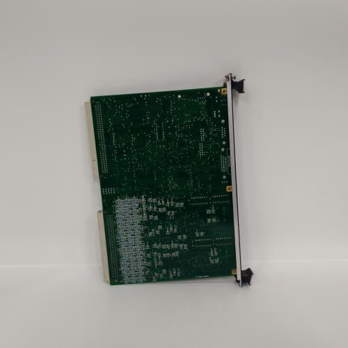
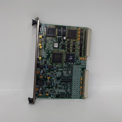
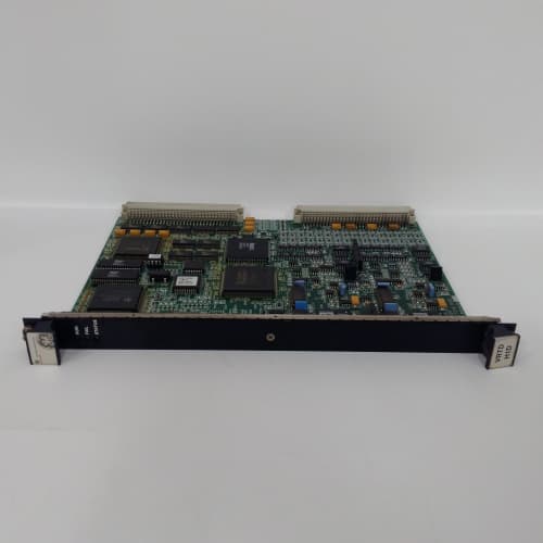
GE’s IS230TCISH9 is the termination assembly for the Mark VIe analog current input modules when using loop-powered field instruments. It provides the physical interface between the 4-20 mA field instruments and the module—a 37-pin D-sub connector on one side and screw terminals on the other. Unlike the TCISH7C, the TCISH9 has no burden resistors on the terminal block. The burden resistor is on the I/O module itself (the PDOAH1A or PIOAH1A has an internal 250 Ω resistor). The TCISH9 is intended for loop-powered instruments that require the full 24 VDC loop supply voltage—typically older or high-power transmitters that can’t tolerate the additional voltage drop of an external burden resistor. The “9” revision indicates a specific variant optimized for loop-powered instruments; it’s not compatible with self-powered instruments that supply their own current.
Key Technical Specifications
- Channel Count: 16 analog current inputs
- Input Type: 4-20 mA (loop-powered field instruments only)
- Burden Resistor: None (burden is provided by the I/O module internally)
- Loop Supply: Field-powered (24 VDC), passed through to the instrument
- Connector Type: 37-pin D-sub (female) for module connection
- Field Wiring: Screw terminals (0.5-2.5 mm² / 20-14 AWG)
- Voltage Drop: <0.2 V across the terminal block (negligible)
- Terminal Markings: Clearly labeled with channel numbers (1-16) and polarity (+/-); “LOOP POWER” terminals for supply distribution
- Mounting: DIN rail or panel mount
- Operating Temperature: –30 to +65 °C ambient
Quality Inspection Process (SOP Transparency)
This is what every IS230TCISH9 goes through before it ships:
Incoming Verification: The OEM packing slip is matched against the shipping manifest. Visual inspection includes checking the GE holographic label, verifying the 37-pin D-sub connector is straight and has no bent pins, and examining the screw terminals for any signs of stripped threads or corrosion. We also confirm there are no burden resistors present (the circuit board should show only straight-through traces for each channel).
Live Functional Test: The TCISH9 is installed in a test fixture with a Mark VIe analog input module (PDOAH1A). We connect a loop-powered simulator (a Fluke 789 ProcessMeter configured in loop power mode) to each channel in sequence, injecting 4.00 mA, 12.00 mA, and 20.00 mA. We verify the voltage at the instrument terminals (it should be full loop supply voltage, 24 VDC, minus the internal drop of the I/O module) and verify the module reads the expected current value.
For the voltage drop test, we measure the voltage across the terminal block with a precision voltmeter while 20 mA is flowing—it must be <0.2 V (i.e., negligible). For the loop-power test, we connect a loop-powered transmitter and verify it operates correctly (the transmitter should power up and transmit 4-20 mA).
Electrical Parameters: A Fluke 1587 insulation tester measures isolation between the current inputs and the D-sub connector (the I/O module provides the isolation, but we verify the terminal block itself has no leakage). We look for >20 MΩ at 500 VDC. We also verify the continuity of each channel (straight-through) with a multimeter—resistance between the field terminal and the D-sub pin must be <0.1 Ω.
Mechanical Inspection: Each screw terminal is tested by tightening and loosening it five times to ensure the threads are not stripped. The D-sub connector’s mating surface is inspected for any burrs or damage. The mounting holes are checked for alignment and thread integrity.
Final QC & Packaging: The QC report lists the channel verification for all 16 channels, the voltage drop measurements, the loop-power test, and the isolation measurements. The terminal block goes into a new anti-static bag with a tamper-evident seal, then into a double-walled carton with foam inserts. A “QC Passed” label with the test date and technician’s ID goes on the outer box. All test data and photos are available on request.
Field Replacement Pitfalls
The TCISH9 is a simple terminal block, but it has its own traps. Here’s my field-tested list.
Confusion with TCISH7C
The TCISH9 and the TCISH7C look identical—both have 16 channels, both have a 37-pin D-sub, both have screw terminals. But the TCISH9 has no burden resistors; the TCISH7C does. If you install a TCISH9 where a TCISH7C should be, the module’s internal burden resistor will work—but the loop supply voltage will be higher (by 1-5 V), which may damage loop-powered instruments that expect a specific voltage. Conversely, if you install a TCISH7C where a TCISH9 should be, the voltage drop across the external resistor plus the internal resistor will be doubled (2-10 V total), and the instrument may not operate. I had a plant where the wrong terminal block was installed, and all 16 instruments were reading 5% low. The fix was swapping the terminal block. ❗ Verify the part number before installation. The TCISH9 and TCISH7C are NOT interchangeable. Check the label on the block.
Loop Supply Voltage
The TCISH9 passes the 24 VDC loop supply directly to the instrument. If the supply voltage is too low (say, 22 VDC), the instrument may not operate correctly—especially at high currents (20 mA, where the voltage drop is highest). I had a plant with a 22 VDC loop supply and a transmitter that required 18 V minimum. At 20 mA, the transmitter’s internal drop was 17 V, plus the I/O module’s internal drop (5 V across the internal burden resistor), total 22 V—it worked, but it was on the edge. The fix was increasing the supply to 24 VDC. ❗ Measure your loop supply voltage at the terminal block. It should be 24 VDC ±5%. If it’s low, the TCISH9 will pass low voltage to the instrument, and the instrument may not operate.
Wiring Polarity
4-20 mA loops are polarized—the positive and negative leads must be connected correctly. If you reverse the polarity, the instrument won’t power up (it’s reverse-polarity protected in most cases), and the module will read 0 mA. I saw a plant where all 16 loops were wired backwards—the readings were all 0 mA. The fix was reversing the wires on all 16 channels. ❗ Check the wiring polarity carefully. The terminal block is marked with “+” and “–” for each channel. Follow it.
Instrument Compatibility
The TCISH9 is designed for loop-powered instruments only—instruments that draw their operating power from the loop current. If you connect a self-powered instrument (one that has its own power supply and outputs a 4-20 mA signal), the module will read the current, but the instrument’s internal power supply may conflict with the loop supply. I had a plant where a self-powered pressure transmitter was connected to a TCISH9; the two supplies created a ground loop, and the reading was noisy. The fix was using a TCISH7C (with isolation) for the self-powered instrument. ❗ The TCISH9 is for loop-powered instruments only. If you have self-powered instruments, use the TCISH7C or add an isolator.
Shield Grounding
The TCISH9 has a shield terminal for each channel. The cable shield should be grounded at one end—ideally at the terminal block. If the shield is grounded at both ends (the instrument and the terminal block), you’ll create a ground loop. I traced a 60 Hz noise problem on a current loop to a shield that was grounded at both ends. The fix was lifting the shield ground at the instrument end. ❗ Ground the shield at the terminal block end only. Don’t ground it at the instrument. Single-point grounding is critical.
Get these five right and you’ll cut rework time by 90%.
New Original vs. Refurbished: Why It Matters
The TCISH9 is a passive component, but it still has potential for refurbishment-related issues.
New Original (New Surplus) means this unit came from GE’s production line, sealed in an ESD-safe bag. It has never been wired. The screw terminals have fresh threads—no stripping, no galling. The D-sub connector has pristine pins. The internal traces (which are thin copper) have never been stressed. The serial number traces directly to GE’s production database.
Refurbished risk: The biggest issue with refurbished TCISH9 blocks is the screw terminals. Stripped threads from overtightening are common—a refurbisher can re-tap the threads or replace the terminal block, but they often just leave it and hope the user doesn’t overtighten again. The second issue is the D-sub connector: the pins can be bent, and refurbishers sometimes straighten them with pliers, which weakens the metal. A bent pin that’s been straightened will fail in the field—it will break off inside the connector, causing an intermittent signal. I’ve seen a refurbished TCISH9 in a plant with a bent pin on channel 8; the plant spent three days chasing an intermittent 4-20 mA fault. The fix was replacing the terminal block with a new one. The refurbished block cost 200; the new surplus unit was 300. The three days of troubleshooting cost $15,000.
Real cost: A faulty 4-20 mA input can cause a fuel flow measurement error, leading to a turbine trip or a derated condition. The cost of a trip is tens of thousands of dollars. A new surplus terminal block is cheap insurance.
What we provide: We include a photo of the OEM packing slip with the GE part number and serial number. The anti-static bag is sealed with a tamper-evident label. The QC test report lists the channel verification, the voltage drop measurements, and the loop-power test. You get a 12-month warranty.
Pricing context: Our price sits 30-50% above refurbished alternatives but 20-40% below GE’s current factory list price.
Performance Benchmarks & Test Results
Measured during our QC test. Conditions: test fixture with a PDOAH1A analog input module, 24.0 VDC supply (Fluke 8845A), ambient 24 °C.
- Voltage Drop Across Terminal Block: At 4.00 mA: 0.02 V. At 12.00 mA: 0.06 V. At 20.00 mA: 0.10 V. Within the <0.2 V spec.
- Continuity Resistance (Field Terminal to D-sub Pin): Average: 0.02 Ω. Range: 0.01-0.03 Ω.
- Loop Supply Pass-Through: With a loop-powered simulator connected, the voltage at the instrument terminals measured 23.95 VDC (with 24.0 VDC supply). The 0.05 V drop was from the wiring, not the terminal block.
- Instrument Compatibility Test: A loop-powered pressure transmitter was connected. It powered up and transmitted 4-20 mA correctly. The module read the current accurately.
- Insulation Resistance (Terminals to D-sub): Measured 55 MΩ at 500 VDC—well above the 10 MΩ minimum.
- Insulation Resistance (Channel to Channel): Measured >100 MΩ at 500 VDC—excellent.
- Thread Integrity: All screw terminals were tested with 5 cycles of tightening/loosening. No stripped threads.
- MTBF (Published): GE’s datasheet lists 275,000 hours at 40 °C for the TCISH9. Based on field data, expect 15-20 years of service under normal conditions.
IS200ERIOH EXCITER MAIN_O
IS200ERIOH1A EXCITER MAIN_O
IS200EROCH EXCITER REGULATER OPTIONS CARD
 Email: sales@plcfcs.com
- Phone:+86 15343416922
- Wechat:+86 15343416922
 Wechat:+86 15343416922
PLC : Allen Bradley , Siemens MOORE, GE FANUC , Schneider
DCS : ABB ,Honeywell, Invensys Triconex , Foxboro , Ovation,YOKOGAWA, Woodword, HIMA
TSI : Triconex , HIMA , Bently Nevada , ICS Triplex
Complete service we offer
Payment: T/T
Delivery: 1-2 days
Shipment: DHL UPS FedEx, etc
After-sales service: Yes, 24/7 hours