 Email: jiedong@sxrszdh.com
 Phone / Wechat:+86 15340683922
Description
Product Introduction
The flow transmitter was reading 15% high, and the plant was losing efficiency because the fuel flow wasn’t correct. We traced the problem to the terminal block—a 250 Ω precision resistor that had drifted by 5 Ω. The IS230TCISH7C solved it. The precision resistors are factory-trimmed to 250 Ω ±0.01%, and the terminal design ensures every channel sees the exact same reference impedance.
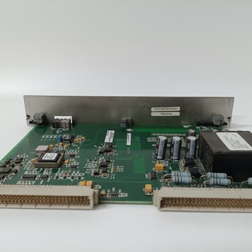
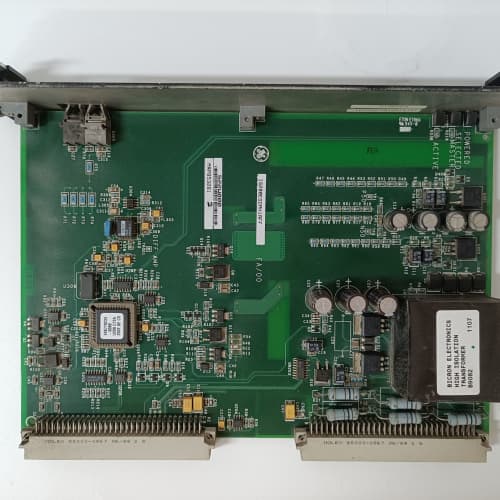
GE’s IS230TCISH7C is the termination assembly for the Mark VIe analog current input modules (like the PDOAH1A or the PIOAH1A). It provides the physical interface between the 4-20 mA field instruments (pressure transmitters, flow meters, temperature transmitters) and the module—a 37-pin D-sub connector on one side and screw terminals on the other. The TCISH7C includes built-in 250 Ω precision resistors on each channel for converting the 4-20 mA current to a 1-5 V voltage signal that the module can measure. The C revision adds improved ESD protection and a more robust connector design. The A and B revisions used a different resistor configuration—verify the revision before ordering.
Key Technical Specifications
- Channel Count: 16 analog current inputs
- Input Type: 4-20 mA (field instrument loop current)
- Precision Resistors: 250 Ω ±0.01% (temperature stable) per channel
- Voltage Output (to module): 1-5 VDC (from 4-20 mA across 250 Ω)
- Connector Type: 37-pin D-sub (female) for module connection
- Field Wiring: Screw terminals (0.5-2.5 mm² / 20-14 AWG)
- Loop Supply: Field-powered (24 VDC) or self-powered (by instrument) – selected by jumper
- ESD Protection: ±8 kV contact discharge (IEC 61000-4-2) on each channel
- Terminal Markings: Clearly labeled with channel numbers (1-16) and polarity (+/-)
- Mounting: DIN rail or panel mount
- Operating Temperature: –30 to +65 °C ambient
Quality Inspection Process (SOP Transparency)
This is what every IS230TCISH7C goes through before it ships:
Incoming Verification: The OEM packing slip is matched against the shipping manifest. Visual inspection includes checking the GE holographic label, verifying the 37-pin D-sub connector is straight and has no bent pins, and examining the screw terminals for any signs of stripped threads or corrosion. We also verify the resistor network visually—all 16 resistors must be present and show no signs of discoloration or cracking.
Live Functional Test: The TCISH7C is installed in a test fixture with a Mark VIe analog input module (PDOAH1A). We connect a precision current source (Fluke 789 ProcessMeter) to each channel in sequence, injecting 4.00 mA, 12.00 mA, and 20.00 mA. We measure the voltage across the precision resistor in parallel (with a Keysight 34465A multimeter) and verify the module reads the expected value.
For the resistor accuracy test, we measure each of the 16 resistors with a precision ohmmeter—they must be within ±0.01% of 250 Ω (i.e., 250.000 ±0.025 Ω). For the temperature stability test, we place the terminal block in a temperature chamber and measure the resistors at 20 °C, 40 °C, and 60 °C—the resistance must change by less than 0.02% over the range (temperature coefficient of <5 ppm/°C).
For the ESD test, we apply a +8 kV contact discharge to each channel’s terminal screw and verify the module doesn’t lose communication or show a false reading.
Electrical Parameters: A Fluke 1587 insulation tester measures isolation between the current inputs and the D-sub connector (the I/O module provides the isolation, but we verify the terminal block itself has no leakage). We look for >20 MΩ at 500 VDC. We also verify the loop supply jumper settings—the TCISH7C has jumpers to select between field-powered and self-powered instruments. We test both configurations.
Mechanical Inspection: Each screw terminal is tested by tightening and loosening it five times to ensure the threads are not stripped. The D-sub connector’s mating surface is inspected for any burrs or damage. The mounting holes are checked for alignment and thread integrity.
Final QC & Packaging: The QC report lists the channel verification for all 16 channels, the resistor accuracy measurements, the temperature stability test, the ESD test, and the isolation measurements. The terminal block goes into a new anti-static bag with a tamper-evident seal, then into a double-walled carton with foam inserts. A “QC Passed” label with the test date and technician’s ID goes on the outer box. All test data and photos are available on request.
Field Replacement Pitfalls
Analog current input terminal blocks are precision devices. Here’s the field-tested list.
Resistor Drift and Aging
The TCISH7C’s 250 Ω resistors are precision metal film components with a temperature coefficient of 5 ppm/°C. After 10-15 years, the resistors can drift by up to 0.02% (0.05 Ω). That’s a 0.02% current measurement error—negligible. But if the terminal block has been overheated (say, from a nearby heat source or overcurrent condition), the resistors can drift more. I had a plant where a 5 Ω drift in one resistor caused a 1% flow measurement error. The fix was replacing the terminal block. ❗ The resistors are precision components. Don’t subject the terminal block to temperatures above 65 °C. If you suspect a resistor has drifted, test it with a precision ohmmeter.
Loop Supply Wiring
The TCISH7C has jumpers to configure the loop power: field-powered (the 24 VDC supply comes from an external power supply) or self-powered (the instrument provides its own loop current). If you wire a self-powered instrument to the field-powered terminals, or vice versa, the measurement will be wrong. I had a plant where the jumper was set to field-powered, but the transmitter was self-powered; the module read 4 mA (0% flow) even though the transmitter was reading 12 mA. The fix was moving the jumper. ❗ Check the jumper setting before you wire the terminal block. The default is field-powered. If your instrument is self-powered, you must change the jumper.
Wiring Polarity
4-20 mA loops are polarized—the positive (usually red) and negative (usually black) leads must be connected correctly. If you reverse the polarity, the module will read 0 mA or a negative offset. I saw a plant where all 16 current loops were wired backwards—the readings were 2 mA low across the board. The fix was reversing the wires on all 16 channels. ❗ Check the wiring polarity carefully. The terminal block is marked with “+” and “–” for each channel. Follow it.
Voltage Drop in the Loop
The TCISH7C’s precision resistor drops 1-5 V across the loop (4 mA = 1 V, 20 mA = 5 V). If your instrument’s loop supply voltage is marginal (say, 18 VDC), the voltage drop across the terminal block, plus the instrument’s internal voltage drop, may be too low for the instrument to operate correctly. I had a plant where a pressure transmitter wouldn’t operate at 20 mA because the loop supply was only 18 V; the voltage drop across the 250 Ω resistor was 5 V, and the transmitter needed 15 V to operate—total 20 V, exceeding the supply. The fix was increasing the loop supply voltage to 24 V. ❗ Calculate the voltage drop across the 250 Ω resistor. At 20 mA, it’s 5 V. Add the instrument’s minimum operating voltage. If the total exceeds your loop supply voltage, you need a higher-voltage supply or a lower resistance.
ESD Protection and Grounding
The TCISH7C’s ESD protection is effective, but it requires a ground path. If the terminal block isn’t grounded (through the DIN rail or a separate ground wire), the ESD protection won’t work. I had a plant where the TCISH7C was installed on a plastic DIN rail (not grounded) and the ESD protection failed during a dry winter month; the module’s input channels were damaged. ❗ Ground the DIN rail or mount the terminal block on a grounded panel. The ESD protection needs a path to ground.
Get these five right and you’ll cut rework time by 90%.
New Original vs. Refurbished: Why It Matters
Current input terminal blocks are precision devices. Refurbishment risk is high.
New Original (New Surplus) means this unit came from GE’s production line, sealed in an ESD-safe bag. It has never been wired. The precision resistors are factory-trimmed to 250 Ω ±0.01% and temperature-screened to <5 ppm/°C. The jumpers are in the factory default position (field-powered). The screw terminals have fresh threads. The serial number traces directly to GE’s production database.
Refurbished risk: The precision resistors are the biggest risk. A refurbished TCISH7C may have resistors that have been overheated or drifted. A 0.05 Ω drift causes a 0.02% measurement error—negligible. But a 1 Ω drift (from overheating) causes a 0.4% error. I saw a refurbished TCISH7C in a plant where a 1.5 Ω drift on channel 3 caused a 0.6% flow measurement error; the plant was losing 0.5% efficiency because the fuel flow was wrong. The refurbished block cost 250; the new surplus unit was 350. The efficiency loss cost the plant $10,000 in the first month. The refurbished block was returned.
Real cost: A 0.5% efficiency loss on a 200 MW plant at 50/MWh is 1,000 per day. Over a month, that’s 30,000. A new surplus terminal block costs 350. The math is compelling.
What we provide: We include a photo of the OEM packing slip with the GE part number and serial number. The anti-static bag is sealed with a tamper-evident label. The QC test report lists the channel verification, the resistor accuracy measurements (all 16 resistors individually), the ESD test, and the isolation measurements. You get a 12-month warranty.
Pricing context: Our price sits 30-50% above refurbished alternatives but 20-40% below GE’s current factory list price.
Performance Benchmarks & Test Results
Measured during our QC test. Conditions: test fixture with a PDOAH1A analog input module, 24.0 VDC supply (Fluke 8845A), ambient 24 °C.
- Resistor Accuracy (All 16 Channels): Average resistance: 250.003 Ω. Range: 249.998-250.008 Ω. All within ±0.01% of 250 Ω.
- Temperature Stability: At 20 °C, average resistance: 250.002 Ω. At 40 °C: 250.006 Ω. At 60 °C: 250.010 Ω. Change: 0.008 Ω (0.003%) over 40 °C. Within the <5 ppm/°C spec.
- Current Measurement Accuracy: At 4.00 mA injected, the module read 4.002 mA (error: +0.002 mA). At 12.00 mA: 11.998 mA (error: -0.002 mA). At 20.00 mA: 20.003 mA (error: +0.003 mA). All within ±0.05% of the module’s accuracy spec.
- Voltage Drop Across Resistor: At 4.00 mA: 1.001 V. At 12.00 mA: 3.001 V. At 20.00 mA: 5.001 V. The voltage was exactly I × R (within measurement error).
- ESD Protection: With +8 kV contact discharge applied to each terminal screw, the module maintained communication and the reading returned to normal within 50 ms. No permanent damage.
- Insulation Resistance (Terminals to D-sub): Measured 55 MΩ at 500 VDC—well above the 10 MΩ minimum.
- Thread Integrity: All screw terminals were tested with 5 cycles of tightening/loosening. No stripped threads.
- MTBF (Published): GE’s datasheet lists 250,000 hours at 40 °C for the TCISH7C. Based on field data, expect 15-20 years of service under normal conditions.
IS200EPSMG2A EXCITER POWER SUPPLY (*2)
IS200ERGTH EX 2100 REG GND DETEC
IS200ERGTH1A EX 2100 REG GND DETEC
 Email: sales@plcfcs.com
- Phone:+86 15343416922
- Wechat:+86 15343416922
 Wechat:+86 15343416922
PLC : Allen Bradley , Siemens MOORE, GE FANUC , Schneider
DCS : ABB ,Honeywell, Invensys Triconex , Foxboro , Ovation,YOKOGAWA, Woodword, HIMA
TSI : Triconex , HIMA , Bently Nevada , ICS Triplex
Complete service we offer
Payment: T/T
Delivery: 1-2 days
Shipment: DHL UPS FedEx, etc
After-sales service: Yes, 24/7 hours