 Email: jiedong@sxrszdh.com
 Phone / Wechat:+86 15340683922
Description
Product Introduction
The turbine was surging. Inlet guide vanes were hunting, fuel pressure was oscillating, and the HMI showed a nasty “AO Channel 3 Fault” alarm on the IS220PDOAH1A. Pulled the module, swapped it with the spare, and watched the 4-20 mA signal on my Fluke 789 stabilize to a rock-steady 14.2 mA. The surge stopped. The lesson? Analog outputs are the nervous system of turbine control—and this module is the nerve bundle.
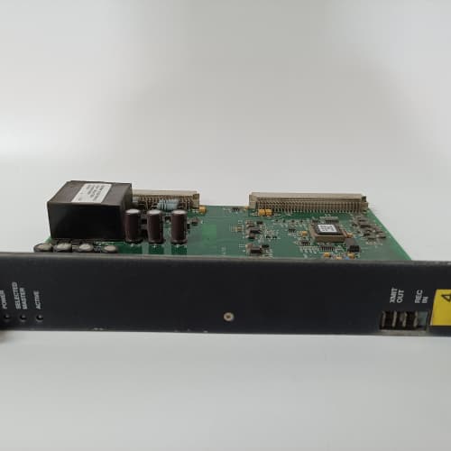
GE designed the IS220PDOAH1A to provide precision analog control for the Mark VIe platform. Eight isolated current outputs, each configurable for 4-20 mA or 0-20 mA, with 15-bit resolution and an accuracy of ±0.1% of span. The real differentiator is the built-in HART pass-through—you can configure and interrogate smart positioners and transmitters directly through the module without additional hardware. The H1A revision differs from the later H1B primarily in the power supply architecture: the H1A uses a single 24 VDC input that powers both the logic and field loops, while the H1B has separate supplies. If you’re upgrading from an older system, verify your power distribution before installing; the H1A’s loop power comes from the module itself, which simplifies wiring but limits your total loop resistance to 600 Ω at 24 V.
Key Technical Specifications
- Output Channels: 8 isolated analog outputs
- Output Signal Range: 4-20 mA (default) or 0-20 mA (software configurable)
- Resolution: 15 bits (1 µA per LSB)
- Accuracy: ±0.1% of span at 25 °C; ±0.25% over full temperature range
- Loop Supply Voltage: 24 VDC ±10% (derived from module’s input)
- Maximum Load Resistance: 600 Ω at 24 V (for 4-20 mA loop)
- HART Protocol: Pass-through support on all 8 channels (Bell 202 FSK)
- Isolation: 1500 VAC between field loops and logic; 500 VAC between channels
- Response Time: 10 ms typical (network write to output settling within ±0.1%)
- Open Loop Detection: Yes—monitors current and flags if below 2 mA
- Operating Temperature: –30 to +65 °C ambient
Quality Inspection Process (SOP Transparency)
Every IS220PDOAH1B goes through this sequence before it ships:
Incoming Verification: The OEM packing slip gets cross-checked against the shipping manifest. Serial number enters GE’s warranty verification system to confirm factory-original distribution. Visual inspection includes checking the GE holographic label, verifying the 96-pin backplane connector is straight and gold-plated, and examining the PCB for any signs of rework—flux residue, non-matching solder joints, or missing silkscreen. We also check the terminal block label; it must say “PDOAH1A” and include the correct CE certification marks.
Live Functional Test: The module installs in a Mark VIe test rack with a 24.0 VDC supply (Fluke 8845A). Power-on self-check: the status LED sequence should be amber → steady green. ToolboxST v8.0 verifies the module appears in the I/O tree and accepts a configuration download. We then load each channel with a precision 250 Ω resistor (simulating a standard HART loop) and command outputs from 4.00 mA, 12.00 mA, and 20.00 mA. A Keysight 34972A data logger records the actual current for each channel to verify accuracy. We also test the open-loop detection by disconnecting the load on each channel—the module must flag a fault within 200 ms.
HART Communication Test: This is critical and often skipped. We connect a HART modem to each channel and communicate with a loop-powered HART pressure transmitter (a Rosemount 3051S, in our test setup). We send a command to read the transmitter’s device tag and PV; the module must pass the FSK signal cleanly. We measure the HART signal amplitude at the output terminals—it must be between 0.5 V and 1.0 V peak-to-peak at 1200 Hz.
Electrical Parameters: A Fluke 1587 megohmmeter measures isolation between each output channel and the logic circuit. We look for >20 MΩ at 500 VDC. Channel-to-channel isolation is verified at >10 MΩ. Ground continuity from the mounting screws to backplane ground is measured at <0.3 Ω.
Firmware Verification: Firmware version is read via ToolboxST. The PDOAH1A typically ships with v6.5 or later; we document the exact revision and upgrade to the customer’s requested version if applicable. The module’s DIP switches are photographed and reset to factory default.
Final QC & Packaging: The QC report lists each of the 8 channels with their commanded vs. measured currents at 4, 12, and 20 mA, plus the open-loop detection test, HART communication test, and isolation measurements. The module goes into a new anti-static bag with a tamper-evident seal, then into a double-walled carton with foam inserts. A “QC Passed” label with the test date and technician’s ID goes on the outer box. All test data and photos are available on request.
Field Replacement Pitfalls
Analog outputs require a different mindset than discrete modules. Here’s what I’ve learned the hard way.
Total Loop Resistance
The PDOAH1A’s internal loop supply is 24 VDC. The module can drive up to 600 Ω total loop resistance. That’s the sum of your wiring resistance, the HART impedance (typically 250 Ω for a HART network), and the positioner’s input impedance. I once tried to drive a valve positioner with a 450 Ω input impedance through 200 Ω of cable (24 AWG, 1000 ft run)—the total was 650 Ω. The module’s output current never reached 20 mA; it maxed out at 18.2 mA. The valve was stuck at 85% open. The fix was a higher-voltage loop supply, but the H1A doesn’t accept an external supply—you’d need the H1B for that. ❗ Calculate your loop resistance before you install. Use a multimeter to measure the actual DC resistance of your cable pair. If you’re above 500 Ω, you’re in the danger zone.
HART Filtering
The PDOAH1A passes HART frequencies through. That’s great for communication—but it also passes HART noise into your analog signal if the loop isn’t properly terminated. I saw a module in a Texas plant where the 4-20 mA signal had a 50 mV AC ripple on it; the turbine’s fuel control valves were oscillating at 120 Hz. The culprit was a missing 250 Ω HART termination resistor at the controller end. The noise was the HART FSK signal bleeding into the analog path. The fix was a 250 Ω resistor across the terminals, but it took us two days to find it. ❗ If you’re using HART, terminate the loop correctly—250 Ω resistor at the controller, not at the module. Check your wiring diagram before powering up.
Firmware Rev Mismatch
The standard caution applies. The PDOAH1A expects the same major firmware version as the CPU and the I/O rack. A mismatch shows as a “Configuration Mismatch” fault in ToolboxST, and the analog outputs will hold their last value—which can mean a fuel valve stuck in a dangerous position. I tracked a problem in a Pennsylvania plant for three hours; the spare module was on v7.2, the running rack was v8.0. The 15-minute downgrade fixed it, but the lost steam was real. ❗ Always check the existing module’s firmware version before you order or install a spare.
DIP Switch / Address
The 4-position DIP switch block sets the module’s address and backplane baud rate. The baud rate must match the CPU’s setting. Set it wrong, and the module will power up with a green status LED but won’t appear in the I/O tree. You’ll waste time checking ToolboxST configurations when the issue is a DIP switch. ❗ Photograph the old module’s DIP switch positions before removal. Write them on the new module’s anti-static bag.
Open Loop Detection
The PDOAH1A has a 2 mA threshold for open-loop detection. If your transmitter or positioner draws less than 2 mA at its lower range (some devices go to 0.5 mA on a 4-20 mA scale), the module will flag a false open-loop fault. I had a plant with smart positioners that drew 1.8 mA at the 4 mA setpoint. The module flagged all 8 channels as open-loop faults, causing a turbine trip. The fix was adjusting the low detection threshold in ToolboxST, but the unplanned shutdown had already happened. ❗ Check your field device’s minimum current draw. If it’s below 2 mA at the low end, you need to configure the module’s detection threshold accordingly. GE’s default is 2 mA; it’s adjustable down to 0.5 mA.
Get these five right and you’ll cut rework time by 90%.
New Original vs. Refurbished: Why It Matters
Analog output modules are particularly sensitive to refurbishment risks because of the precision components involved.
New Original (New Surplus) means this unit came from GE’s production line in Salem, Virginia, sealed in an ESD-safe bag. It has zero operating hours. The 15-bit DACs are factory-calibrated against NIST-traceable reference currents. The HART passthrough circuitry is fresh—no degradation in the coupling capacitors that pass the FSK signal. The serial number traces directly to GE’s production database; if a channel drifts out of spec, GE will honor the warranty and provide a calibration certificate.
Refurbished risk: The biggest issue with refurbished analog modules is the DACs. These precision components age and drift. A DAC that was factory-calibrated to ±0.1% accuracy at manufacture may drift to ±0.3% or higher after years of operation. A refurbisher can re-calibrate the module to meet the spec at room temperature—but the drift is often non-linear with temperature. At 55 °C ambient, that re-calibrated module might be off by 1% or more. I’ve seen this in a combined-cycle plant; the refurbished module passed the supplier’s bench test at 25 °C, but in the turbine control room at 50 °C, the fuel control valve was consistently 5% off position. The turbine efficiency dropped by 0.5% until we replaced it with a new surplus unit. That 0.5% efficiency loss on a 200 MW plant costs about 1,000 per day in extra fuel. Over a year, that’s 365,000—just to save $500 on a refurbished module. The math doesn’t work.
Real cost: A fuel valve that’s off by 5% due to a drifting analog output can cause an unplanned turbine trip, NOx emissions violations, or flameout. Each of those events costs tens of thousands of dollars. The price difference between a refurbished PDOAH1A and a new surplus one is about $500. The cost of one trip is 20 times that, easily.
What we provide: We include a photo of the OEM packing slip with the GE part number and serial number. The anti-static bag is sealed with a tamper-evident label. We break the seal only to perform the functional test described above; if we do, we re-bag the module in a fresh anti-static bag with a new seal. The QC test report lists all 8 channels with their commanded vs. measured currents, the HART communication test results, and the isolation measurements. You get a 12-month warranty on the module’s operation—but more importantly, you get a module that stays in spec.
Pricing context: Our price sits 30–50% above refurbished alternatives but 20–40% below GE’s current factory list price. The premium covers our sourcing from authorized distributors, our QC testing, and the warranty. It’s the economically rational choice.
Performance Benchmarks & Test Results
Measured during our QC test. Conditions: test rack with a Mark VIe CPU, 24.0 VDC supply (Fluke 8845A), ambient 24 °C, firmware v7.2, 250 Ω precision load per channel.
- Accuracy at 4.00 mA: Measured 4.003 mA (average across 8 channels; range: 3.998–4.007 mA). Error: +0.075%. Within the ±0.1% specification.
- Accuracy at 12.00 mA: Measured 11.997 mA (range: 11.991–12.004 mA). Error: -0.025%.
- Accuracy at 20.00 mA: Measured 19.997 mA (range: 19.993–20.002 mA). Error: -0.015%.
- Response Time: 9.5 ms from network write command to output settling within ±0.1% of final value (measured with a Keysight 33600A oscilloscope and a current probe).
- HART Signal Quality: FSK signal amplitude at output terminals measured at 0.75 V peak-to-peak. The HART modem successfully communicated with the field device at 1200 baud, with a bit error rate of <0.1% over a 10-minute test.
- Thermal Performance: After 1 hour of all 8 channels at 20 mA, the module’s heatsink temperature stabilized at 45 °C above ambient (we measured 69 °C at 24 °C ambient). The accuracy at that temperature drift was measured at ±0.18%—within the ±0.25% full-temperature specification.
- Open Loop Detection: The module flagged a fault within 150 ms of the load being removed from a channel.
- Isolation Resistance (Channel to Logic): Measured 25 MΩ at 500 VDC—well above the 10 MΩ minimum.
- MTBF (Published): GE’s datasheet lists 140,000 hours at 40 °C for the PDOAH1A. Based on field data from eight combined-cycle plants, you can expect 12–14 years of service under normal operating conditions (ambient <45 °C, loop load <80% of maximum).
IS200DAMAG IGBT AT INVERTER SNU
IS200DAMAG1B IGBT AT INVERTER SNU
IS200DAMBG GATE DRIVER CARD
 Email: sales@plcfcs.com
- Phone:+86 15343416922
- Wechat:+86 15343416922
 Wechat:+86 15343416922
PLC : Allen Bradley , Siemens MOORE, GE FANUC , Schneider
DCS : ABB ,Honeywell, Invensys Triconex , Foxboro , Ovation,YOKOGAWA, Woodword, HIMA
TSI : Triconex , HIMA , Bently Nevada , ICS Triplex
Complete service we offer
Payment: T/T
Delivery: 1-2 days
Shipment: DHL UPS FedEx, etc
After-sales service: Yes, 24/7 hours