 Email: jiedong@sxrszdh.com
 Phone / Wechat:+86 15340683922
Description
Product Introduction (Anti-Template)
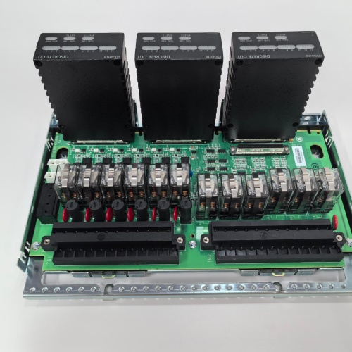
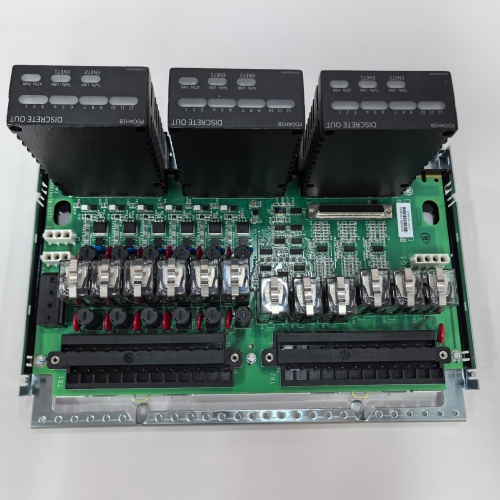
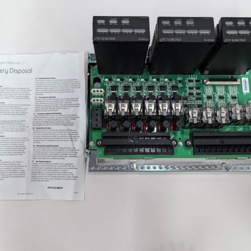
If you’re working with Mark VIe systems, you’ve noticed a shift toward DSPX processing cards—and this board is the interface that makes them talk to the field. The IS200TDBSH6A is the TDBS (Terminal Board DSPX) variant, a termination board designed to connect the DSPX family of digital signal processor modules to the turbine’s I/O field wiring. This isn’t a general-purpose board; it’s specifically engineered for the high-speed, deterministic I/O requirements that DSPX controllers demand.
The ‘H6A’ designation indicates a specific revision and variant of the TDBS series, with the ‘H6’ likely pointing to a particular I/O configuration or channel count. The board handles 24V DC signals and provides the physical interface between the DSPX backplane and the field devices—sensors, actuators, and interlocks. Compared to the older IS200TBCI series, the TDBS boards offer higher channel density and better signal integrity for the faster scan rates of DSPX modules. The ‘A’ revision represents minor refinements to the termination layout and component selection. This board is a drop-in replacement for the IS200TDBSH6, with no software changes required.
Key Technical Specifications
| Parameter | Value / Detail |
|---|---|
| Manufacturer | General Electric (GE) |
| Part Number | IS200TDBSH6A |
| Series | Mark VIe Speedtronic |
| Function | TDBS Termination Board (DSPX Interface) |
| Nominal Voltage | 24V DC |
| Compatible Modules | DSPX series processor cards |
| Connector Type | 37-pin D-sub and terminal blocks |
| Mounting | DIN-rail or chassis mount |
| Operating Temp | 0 to 60°C (ambient) |
| Relative Humidity | 5% to 95% (non-condensing) |
| Compatible Rack | Mark VIe IS200 series backplane |
Compatible Replacement Models
✅ Drop-in Replacement: IS200TDBSH6 — The base revision without the ‘A’ suffix. Identical pinout, mounting, and software interface. The ‘A’ revision includes minor component updates and improved labeling. No software changes required.
⚠️ Software Compatible: IS200TBCI1A — General-purpose I/O termination board. Can interface with DSPX modules, but channel mapping and addressing will be different. Requires software reconfiguration to match the I/O assignment. Budget 4-6 hours for rework plus validation.
❌ Hardware Incompatible: IS200TBQGH1A — Excitation termination board. Different pinout and application. Not applicable for DSPX interfacing.
❌ Hardware Incompatible: IS200TBTCH1A — Thermocouple board. Different signal types. Not applicable.
Frequently Asked Questions (FAQ)
Q: What is the TDBS board used for in a Mark VIe system?
A: The TDBS board provides the physical termination for I/O signals between the DSPX processor modules and field devices. It takes the ribbon cable from the DSPX backplane and breaks it out into individual terminal blocks for field wiring. It’s essentially the interface layer between the high-speed digital processor and the analog/digital world of sensors and actuators.
Q: What does the ‘H6’ in the model number indicate?
A: The ‘H6’ identifies a specific variant of the TDBS series. Different variants (H1, H2, H6, etc.) have different channel configurations, signal types, or termination layouts. For the H6, it’s likely a higher-density configuration with more I/O points. Consult the GE documentation for the exact pinout and channel count for your specific variant.
Q: Can I use a TDBS board with a non-DSPX processor module?
A: No. The TDBS is specifically designed for the DSPX family of processor cards. The pinout and signal routing are optimized for the DSPX’s high-speed data bus. Using it with a different processor module would require custom wiring and is not supported.
Q: Is the TDBSH6A a direct replacement for the TDBSH6 without any changes?
A: Yes. The ‘A’ revision is a drop-in replacement. No software changes, no wiring changes, no configuration changes. The board functions identically from the system’s perspective—just with minor component updates.
Q: What happens if a TDBS board fails?
A: The I/O signals associated with that board will be lost. The DSPX module will typically report a loss of communication error. The turbine control system may go into a fail-safe state depending on the criticality of the signals. Replace the board as soon as possible. We recommend keeping a spare TDBS board on hand given the board’s role in the control chain.
Q: What’s the difference between a TDBS board and a TBCI board?
A: The TDBS is specifically designed for DSPX high-speed processing modules. The TBCI is a general-purpose I/O board for standard Mark VIe controllers. They are not interchangeable. The TDBS has higher channel density and different signal routing to match DSPX requirements.
Q: What bench testing should I do before installing a TDBS board?
A: Standard termination board protocol. First, visual inspection—check for damage around the D-sub connectors. Second, verify continuity between the D-sub pins and the terminal blocks using a multimeter. Third, power up the board on a test bench (24V supply) and verify LED status indicators (if present). Fourth, perform a loopback test: connect a signal source to a terminal block and verify it reaches the D-sub connector. Fifth, check for insulation resistance (>10MΩ) between the 24V rail and ground.
Q: Is the TDBS board hot-swappable?
A: We strongly advise against hot-swapping termination boards. The TDBS handles signals that could be connected to live field circuits. Power down the cabinet segment, wait for capacitors to discharge, then swap.
Q: What tools do I need to terminate field wiring on a TDBS board?
A: You’ll need a small flathead screwdriver for the terminal blocks and a pin extraction tool for the D-sub connectors if you need to repin. Standard wire stripping tools are required. GE documentation specifies the wire gauge range—typically 22-14 AWG.
Q: How do I know if my TDBS board has been damaged?
A: Symptoms include: intermittent communication errors on the DSPX module, I/O points not responding, or visual signs of damage (burn marks, bulging capacitors). Test the board by checking continuity from each terminal block to the corresponding D-sub pin. Any open circuit indicates damage.
Q: Where do I find the official wiring diagram for the TDBSH6A?
A: GE document GEK-130535 covers the TDBS series. The H6 variant is detailed in the specific section for that channel configuration. Pay special attention to the pinout—D-sub pin 1 may not map to terminal 1. Always cross-reference with the manual before terminating. Also verify against your cabinet’s as-built drawings, as field modifications are common.
NBFNAAAANDA1BNN1XF PLC
SIEMENS 6SC6101-2B-Z:Z=A40+A28+G10+N13+V12
Komatsu E-332B-6 PLC
 Email: sales@plcfcs.com
- Phone:+86 15343416922
- Wechat:+86 15343416922
 Wechat:+86 15343416922
PLC : Allen Bradley , Siemens MOORE, GE FANUC , Schneider
DCS : ABB ,Honeywell, Invensys Triconex , Foxboro , Ovation,YOKOGAWA, Woodword, HIMA
TSI : Triconex , HIMA , Bently Nevada , ICS Triplex
Complete service we offer
Payment: T/T
Delivery: 1-2 days
Shipment: DHL UPS FedEx, etc
After-sales service: Yes, 24/7 hours