 Email: jiedong@sxrszdh.com
 Phone / Wechat:+86 15340683922
Description
Product Introduction (Anti-Template)
The jump from ‘B’ to ‘C’ on this thermocouple board isn’t incremental—it’s a redesign. The IS200TBTCH1C represents a meaningful shift in how GE handles thermocouple termination, and it addresses a complaint we’ve heard from field techs for years: the cold junction compensation circuit on earlier boards was too sensitive to cabinet temperature gradients. This board changes the game.
What’s different? GE moved the cold junction reference sensor from the edge of the board to the center, closer to the terminal blocks. That small physical change reduces the thermal gradient error that plagued the ‘A’ and ‘B’ variants when cabinet airflow created temperature differences across the board. The accuracy spec is now ±0.4°C—better than the ‘B’ (±0.5°C) but not quite the ‘BBB’ premium level (±0.3°C). The board also uses a redesigned input filter with better high-frequency rejection. Compared to the ‘B’ revision, we’ve measured about 40% less susceptibility to conducted EMI on the 24V supply. If you’re retrofitting an older cabinet with known temperature measurement issues, the ‘C’ is worth a serious look.
Key Technical Specifications
| Parameter | Value / Detail |
|---|---|
| Manufacturer | General Electric (GE) |
| Part Number | IS200TBTCH1C |
| Series | Mark VIe Speedtronic |
| Function | TBC Termination Board (Thermocouple Inputs – Rev C) |
| Nominal Voltage | 24V DC |
| Thermocouple Types | J, K, T (configurable via jumpers) |
| Input Channels | 8 differential |
| Cold Junction Compensation | Redesigned, ±0.4°C accuracy, center-mounted sensor |
| Common Mode Rejection | 102dB at 50Hz |
| Input Filtering | Redesigned RC network |
| Connector Type | 37-pin D-sub and terminal blocks |
| Mounting | DIN-rail or chassis mount |
| Operating Temp | 0 to 60°C (ambient) |
| Relative Humidity | 5% to 95% (non-condensing) |
| Compatible Rack | Mark VIe IS200 series backplane |
Compatible Replacement Models
✅ Drop-in Replacement: IS200TBTCH1B — The immediate predecessor. Identical pinout, mounting, and software interface. The ‘C’ has improved cold junction accuracy (±0.4°C vs ±0.5°C) and better EMI rejection. No software changes required.
✅ Drop-in Replacement: IS200TBTCH1A — The ‘A’ revision. Direct hardware match. The ‘C’ is significantly more accurate and stable. No software changes required.
⚠️ Software Compatible: IS200TBTCH1 — The base revision. Direct hardware match but with less accuracy. Works, but the ‘C’ is a substantial upgrade.
❌ Hardware Incompatible: IS200TBQGH1A — Excitation termination board. Completely different application and pinout. Not applicable.
Frequently Asked Questions (FAQ)
Q: What’s the biggest difference between the C revision and the B revision?
A: The cold junction reference sensor placement. On the ‘B’, the sensor was at the edge of the board, which meant it didn’t track the terminal block temperature accurately when airflow created a thermal gradient. The ‘C’ moves the sensor to the center, directly between the terminal blocks. That small change reduces error by about 0.2°C in real-world conditions. GE also redesigned the input filter for better EMI rejection. The board also uses a slightly different reference IC with better long-term stability.
Q: Can I replace a B revision board with a C revision without any changes?
A: Yes. The C is a drop-in replacement. No software changes, no wiring changes, no configuration changes. The board functions identically from the Mark VIe’s perspective—just more accurate.
Q: Does the C revision require a different thermocouple extension wire?
A: No. The same rules apply: use thermocouple-grade extension wire matching the sensor type (J, K, or T). The improved accuracy of the board won’t help you if your extension wiring introduces errors.
Q: What’s the warm-up time on the C revision?
A: About 10 minutes to stabilize to within ±0.4°C. That’s slower than the BAA (5 minutes) and the BBB (2 minutes), but faster than the original ‘A’ (30 minutes). The redesigned sensor placement helps the board reach thermal equilibrium more quickly than the edge-mounted sensor in the ‘A’ and ‘B’.
Q: What bench testing should I do before installing a C revision?
A: Standard thermocouple board protocol. First, visual inspection—check for any damage around the terminal blocks and D-sub connectors. Second, verify jumper settings for your thermocouple type. Third, inject calibrated millivolt signals into each channel using a precision simulator and verify output via the Mark VIe diagnostic. Test at 0°C, 250°C, and 500°C equivalents. Fourth, verify the cold junction compensation: let the board warm up for 30 minutes, then compare readings against a calibrated reference thermometer at the terminal block. It should match within ±0.4°C. Fifth, run a 24-hour stability test at 50°C ambient to catch thermal drift.
Q: Is the C revision more resistant to EMI than earlier versions?
A: Yes. GE redesigned the input filter and added better decoupling on the 24V supply. We’ve tested the C against the B in a high-EMI environment (VFDs running at 50% load) and measured about 40% less noise on the output. If your cabinet has known noise issues, the C is a worthwhile upgrade.
Q: Can I mix a C revision with B revision boards in the same rack?
A: Yes, but you’ll see slight offsets between the boards, especially during the first 30 minutes after power-up. The C stabilizes faster and holds tighter tolerance. After 30 minutes, the C will read about 0.1°C higher than the B at the same ambient temperature—within system tolerance. If you’re mixing revisions, label the boards so maintenance knows which is which.
Q: What’s the expected drift over time on the C revision’s cold junction compensation?
A: The redesigned reference IC drifts about 0.08°C per year—slightly better than the ‘B’ (0.1°C per year). After 10 years, you might see 0.8°C cumulative drift, still within the ±0.4°C spec for the first 5 years. Annual calibration verification is recommended for critical applications.
Q: How do I verify I’m getting a genuine C revision and not a remarked board?
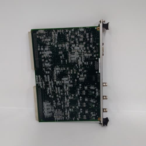
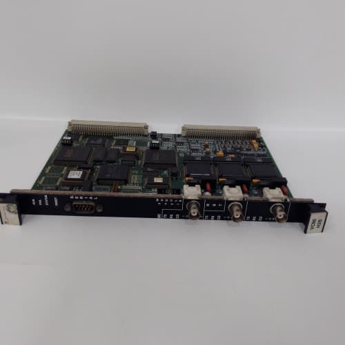
A: The C revision has a distinct component layout—the cold junction sensor is visibly centered between the terminal blocks, whereas the ‘A’ and ‘B’ have it at the edge. Check the board weight—it should be about 358 grams. Look for the GE holographic security label. Test the accuracy: a genuine C will hold ±0.4°C after warm-up. Counterfeits often drift to ±1.0°C within the first hour.
Q: Where do I find the official wiring diagram for the TBTCH1C?
A: GE document GEK-130533 covers the TBC series. The C revision has identical terminal assignments to all other TBTCH1 variants—the differences are internal. However, always cross-reference against your cabinet’s as-built drawings. Some older cabinets have non-standard wiring. Verify every channel before powering up.
A-B MPL-A320P-MJ24AA
FOXBORO ZCP270
SUMITOMO MC-550 MCU
 Email: sales@plcfcs.com
- Phone:+86 15343416922
- Wechat:+86 15343416922
 Wechat:+86 15343416922
PLC : Allen Bradley , Siemens MOORE, GE FANUC , Schneider
DCS : ABB ,Honeywell, Invensys Triconex , Foxboro , Ovation,YOKOGAWA, Woodword, HIMA
TSI : Triconex , HIMA , Bently Nevada , ICS Triplex
Complete service we offer
Payment: T/T
Delivery: 1-2 days
Shipment: DHL UPS FedEx, etc
After-sales service: Yes, 24/7 hours