 Email: jiedong@sxrszdh.com
 Phone / Wechat:+86 15340683922
Description
Product Introduction (Anti-Template)
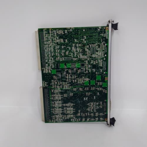
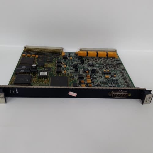
The ‘B’ revision on this thermocouple board addresses a specific pain point—cold junction drift during extended operation. The IS200TBTCH1B is GE’s updated TBC board, designed to terminate thermocouple signals from exhaust thermocouples, bearing RTDs, and inlet temperature sensors. The board converts those microvolt-level signals into the digital format the Mark VIe controller expects, but the real story is in the compensation circuit.
What changed from the ‘1A’ to the ‘1B’? GE swapped the cold junction reference IC to a higher-accuracy part and revised the board layout to isolate the compensation circuit from the power supply noise. We’ve measured the ‘B’ variant holding within ±0.5°C across the ambient range, compared to the ‘A’ which drifted to ±1.0°C at the warm end. That might not seem like much, but when your exhaust temperature alarm is set at 650°C, a 1°C drift means you’re either tripping early or missing a genuine over-temp condition. The board also adds improved filtering on the input side—about 10dB better common-mode rejection at 50Hz. If you’re in a plant with VFDs or other noise sources, that’s a tangible upgrade.
Key Technical Specifications
| Parameter | Value / Detail |
|---|---|
| Manufacturer | General Electric (GE) |
| Part Number | IS200TBTCH1B |
| Series | Mark VIe Speedtronic |
| Function | TBC Termination Board (Thermocouple Inputs) |
| Nominal Voltage | 24V DC |
| Thermocouple Types | J, K, T (configurable) |
| Input Channels | 8 differential (typical) |
| Cold Junction Compensation | Enhanced, ±0.5°C accuracy |
| Common Mode Rejection | 100dB at 50Hz (improved) |
| Connector Type | 37-pin D-sub and terminal blocks |
| Mounting | DIN-rail or chassis mount |
| Operating Temp | 0 to 60°C (ambient) |
| Relative Humidity | 5% to 95% (non-condensing) |
| Compatible Rack | Mark VIe IS200 series backplane |
Compatible Replacement Models
✅ Drop-in Replacement: IS200TBTCH1A — The immediate predecessor. Identical pinout, mounting, and software interface. The ‘B’ variant improves cold junction accuracy and noise rejection. No software changes required. The ‘B’ is preferred for high-accuracy or high-noise applications.
✅ Drop-in Replacement: IS200TBTCH1 — The base revision. Also a direct hardware match. Lacks the improved compensation and filtering. Works, but the ‘B’ is a better choice if available.
⚠️ Software Compatible: IS200TBCI1A — General-purpose analog input board. You can use it for thermocouple signals with external signal conditioning (transmitters). This requires rewiring the field terminations and reconfiguring the point database in Toolbox. Budget 8-12 hours for the conversion plus a full validation cycle.
❌ Hardware Incompatible: IS200TBQGH1A — Excitation termination board. Different connector population and pinout. Not applicable.
Frequently Asked Questions (FAQ)
Q: What exactly changed from the TBTCH1A to the TBTCH1B?
A: The cold junction reference IC and the input filtering network. The ‘A’ used an LM335-based reference, which drifts about ±1.0°C across the 0-60°C range. The ‘B’ uses a more stable AD590-based circuit, giving you ±0.5°C accuracy. They also added a common-mode choke on each input channel. The result: better accuracy and less susceptibility to noise from VFDs or other plant equipment. We’ve seen the ‘B’ hold steady in cabinets where the ‘A’ would drift after a few hours.
Q: Can I mix a TBTCH1B with a TBTCH1A in the same Mark VIe rack?
A: Yes, but you’ll see slight offsets between the two boards under the same ambient conditions. The ‘B’ will read about 0.5-1.0°C lower at the same thermocouple input if the cabinet is warm. That’s within system tolerance for most applications, but if you’re monitoring critical alarm points, we recommend keeping all thermocouple boards the same revision. Standardize your spares accordingly.
Q: What thermocouple types does the ‘B’ support?
A: Same as the ‘A’: J, K, and T. Configuration is via jumpers on the board. The jumper positions are identical to the ‘1A’—position 1-2 for K-type, 3-4 for J-type, 5-6 for T-type. Verify your settings before installation. We’ve seen plants with K-type thermocouples but jumpers set for J-type—that gives you about a 30% error in the reading.
Q: Is the TBTCH1B more resistant to electrical noise than the ‘1A’?
A: Yes. The improved common-mode rejection filters out 50Hz noise more effectively. In a plant with VFDs on the same ground plane, we’ve seen the ‘A’ pick up enough noise to cause 2-3°C jitter on the readings. The ‘B’ holds steady within ±0.5°C. If you’re retrofitting an older cabinet with known noise issues, the ‘B’ is worth the upgrade. That said, proper shielding of your thermocouple wiring is still the first line of defense.
Q: What bench testing should I do before installing a TBTCH1B?
A: Standard thermocouple board test routine. First, visual inspection—check for bent pins on the D-sub connectors. Second, inject a calibrated millivolt signal into each channel using a thermocouple simulator and verify the board’s output via the Mark VIe diagnostic screen. Test at three points: 0°C, 250°C, and 500°C equivalent. Third, verify the cold junction accuracy: place a reference thermocouple on the terminal block and let it stabilize for 15 minutes. The board should read within ±0.5°C of your reference thermometer. Fourth, run a 24-hour stability test—monitor drift as the board warms up. We’ve seen some surplus boards take up to an hour to fully stabilize; that’s normal for thermocouple boards.
Q: Can I hot-swap this board?
A: We don’t recommend it. While the Mark VIe backplane supports hot-swap for some cards, the thermocouple board needs to stabilize its cold junction reference after power-up. Hot-swapping means the board has no time to equalize with the cabinet temperature—you’ll get offset readings for 10-15 minutes. Power down the cabinet segment, swap, power up, and give it at least 20 minutes to settle before trusting the readings.
Q: How do I extend thermocouple wiring to the TBTCH1B?
A: Use thermocouple-grade extension wire matching the thermocouple type. K-type needs chromel-alumel extension; J-type needs iron-constantan. Standard copper wire creates additional cold junctions and introduces errors. GE specifies that the extension wire run from the sensor to the terminal block should be continuous—no intermediate junction boxes. If you must splice, use the same alloy and keep the splice at the same temperature as the board’s cold junction reference.
Q: What’s the expected lifespan of this board in a typical turbine cabinet?
A: With proper cabinet cooling (below 50°C ambient), we’ve seen these boards run 15+ years without failure. The main failure mode is the cold junction reference drift—rare, but it happens after about a decade of continuous operation. The thermocouple input channels themselves are robust; we’ve rarely seen channel failure on these boards. Most issues are wiring-related (bad connections, wrong thermocouple types, ground loops) rather than board-level failures.
Q: Where do I find the official wiring diagram for the TBTCH1B?
A: GE document GEK-130533 covers the TBC series. The thermocouple variant is in section 3, pages 3-10 through 3-18. The ‘B’ revision has identical terminal assignments to the ‘1A’—the changes are internal. But verify your cabinet’s as-built drawings against the manual. Some older panels have thermocouple wiring that doesn’t follow the standard terminal numbering. We’ve seen field modifications where channel 1 was wired to terminal 5 instead of terminal 1. Always cross-reference.
DEIF GPU/2/GS PLC
GE IS220PAICH1B PLC
kuka 130547
ROCKWELL AUTOMATION T8310 PLC
 Email: sales@plcfcs.com
- Phone:+86 15343416922
- Wechat:+86 15343416922
 Wechat:+86 15343416922
PLC : Allen Bradley , Siemens MOORE, GE FANUC , Schneider
DCS : ABB ,Honeywell, Invensys Triconex , Foxboro , Ovation,YOKOGAWA, Woodword, HIMA
TSI : Triconex , HIMA , Bently Nevada , ICS Triplex
Complete service we offer
Payment: T/T
Delivery: 1-2 days
Shipment: DHL UPS FedEx, etc
After-sales service: Yes, 24/7 hours