 Email: jiedong@sxrszdh.com
 Phone / Wechat:+86 15340683922
Description
Product Introduction (Anti-Template)
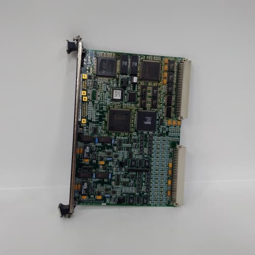
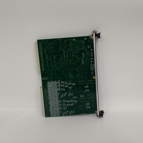
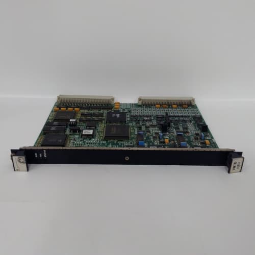
Temperature data is the nervous system of turbine control—and this board is where those millivolt signals land. The IS200TBTCH1A is the TBC (Terminal Board Thermocouple) variant for the Mark VIe system, and it handles the termination of thermocouple inputs from bearing RTDs, exhaust gas thermocouples, and inlet air temperature sensors. This board converts those low-level analog signals into a format the controller can actually use.
The ‘H1A’ suffix matters because thermocouple termination is notoriously fussy. The board includes a cold junction compensation circuit that references the terminal block temperature—crucial for accurate readings. Earlier revisions had drift issues with that compensation as the board warmed up; the ‘A’ revision tightens the compensation curve by about 1.5°C across the operating range. Compared to the IS200TBCI (analog I/O) board, this one is purpose-built for thermocouples—you get better common-mode rejection and dedicated filtering for each channel. That’s the difference between a turbine that trips at 650°C because it reads 652°C, and one that actually knows when it’s at 650°C.
Key Technical Specifications
| Parameter | Value / Detail |
|---|---|
| Manufacturer | General Electric (GE) |
| Part Number | IS200TBTCH1A |
| Series | Mark VIe Speedtronic |
| Function | TBC Termination Board (Thermocouple Inputs) |
| Nominal Voltage | 24V DC |
| Thermocouple Types | J, K, T (configurable) |
| Input Channels | 8 differential (typical) |
| Cold Junction Compensation | Integrated on-board |
| Connector Type | 37-pin D-sub and terminal blocks |
| Mounting | DIN-rail or chassis mount |
| Operating Temp | 0 to 60°C (ambient) |
| Relative Humidity | 5% to 95% (non-condensing) |
| Compatible Rack | Mark VIe IS200 series backplane |
Compatible Replacement Models
✅ Drop-in Replacement: IS200TBTCH1 — The base revision without the ‘A’ suffix. Identical pinout, mounting, and software interface. The ‘A’ revision adds improved cold junction compensation and updated component selection. No software changes required.
⚠️ Software Compatible: IS200TBCI1A — This is a general-purpose analog input board, not thermocouple-specific. You can use it to read thermocouple signals if you add external signal conditioning (transmitters or amplifiers). This requires a complete rewiring of the field terminations and a reconfiguration of the point database in the Mark VIe Toolbox. Budget 8-12 hours for the hardware and software rework, plus validation.
❌ Hardware Incompatible: IS200TBQGH1A — Excitation termination board. Different pinout, different application. Connector population is different. Do not attempt.
Frequently Asked Questions (FAQ)
Q: What thermocouple types does the TBTCH1A support?
A: J, K, and T types. The board uses jumpers or DIP switches to configure each channel for the specific type. The default from the factory is K-type. Check the configuration before installation—we’ve seen plants receive boards with the wrong jumper settings and spend hours chasing erroneous readings.
Q: How accurate is the cold junction compensation on this board?
A: The spec is ±1.0°C across the 0-60°C ambient range. In practice, we’ve seen the ‘A’ revision hold within ±0.8°C. The earlier ‘1’ revision could drift up to ±2.5°C at the warm end. If your turbine exhaust monitoring requires high accuracy, the ‘A’ is worth the upgrade. That said, the board’s cold junction accuracy depends on the actual terminal block temperature—if your cabinet has a hot spot, you’ll see offset errors regardless of the compensation circuit.
Q: Can I use this board for RTD inputs instead of thermocouples?
A: No. RTDs require a different excitation current and signal conditioning. This board is strictly for thermocouple signals. If you have RTD inputs (like bearing temperature sensors), you need the IS200TRTD1A or a dedicated RTD input module. Trying to force an RTD through this board will give you garbage readings.
Q: What bench testing should I do before installing a TBTCH1A?
A: Standard thermocouple termination board test. First, visual inspection—look for any damage around the terminal blocks. Second, inject a precision millivolt source (using a calibrated thermocouple simulator) into each channel and verify the board’s output via the Mark VIe diagnostic screen. Check at three points: 0°C, 250°C, and 500°C equivalent millivolts. Third, verify the cold junction compensation: place a thermocouple on the terminal block, let it stabilize, and compare the board’s reading against a reference thermometer at the block. It should match within ±1.0°C. Fourth, run a 24-hour stability test—cycle the ambient temperature in the test chamber from 0°C to 60°C and monitor channel drift.
Q: Is the TBTCH1A susceptible to electrical noise?
A: Yes, thermocouple signals are inherently low-level (microvolts per degree). The board includes filtering on each input, but field wiring is critical. Use shielded twisted-pair cable for each thermocouple run. Ground the shield at the termination board end only—grounding both ends creates ground loops. We’ve seen plants with unshielded runs of 50 meters pick up enough 50Hz noise to cause intermittent trips. Shielding solves 90% of those issues.
Q: Can I extend the thermocouple wiring beyond the board?
A: No, not with standard copper wire. Thermocouples require the same alloy material for extension leads (type J uses iron-constantan, type K uses chromel-alumel). If you use standard copper wire, you create additional cold junctions that introduce errors. GE specifies using thermocouple-grade extension wire from the field sensor all the way to the TBTCH1A terminal block. Any junction point introduces potential error.
Q: What happens if the cold junction compensation fails?
A: You’ll see a constant offset across all channels. The offset will drift with cabinet temperature. We’ve seen a failed compensation circuit cause all exhaust readings to read 8°C low on a warm day. The board doesn’t typically fail this way, but if you suspect it, compare one channel against a known reference (a handheld thermocouple reader at the same point). If the offset changes as the cabinet warms up, the compensation is suspect. Replace the board.
Q: Where do I find the official wiring diagram for the TBTCH1A?
A: GE document GEK-130533 covers the TBC series. The thermocouple variant is detailed in section 3, pages 3-10 through 3-18. Pay close attention to the thermocouple type selection jumpers—the positions aren’t intuitive. Jumper 1-2 is K-type, 3-4 is J-type, 5-6 is T-type. The manual also specifies which terminal block positions correspond to each D-sub pin. Don’t guess—we’ve seen field techs miswire channel 3 to channel 4 and spend a day tracking down the mismatch.
Q: Is the TBTCH1A a hot-swappable board?
A: Technically the Mark VIe backplane supports it, but we advise against it for thermocouple boards. The cold junction compensation circuit needs time to stabilize after power-up. If you hot-swap, you get a cold junction reading that doesn’t match the actual block temperature for the first 10-15 minutes. That means all your temperature readings will be offset during that period. Power down the cabinet segment, swap the board, power up, and give it 20 minutes to stabilize before relying on the readings.
ABB PPD113B01-10-150000
ELAU PMC-2/11/05/000/00/00/01/00/00 PLC
GE DS200TCPDG2B PLC
 Email: sales@plcfcs.com
- Phone:+86 15343416922
- Wechat:+86 15343416922
 Wechat:+86 15343416922
PLC : Allen Bradley , Siemens MOORE, GE FANUC , Schneider
DCS : ABB ,Honeywell, Invensys Triconex , Foxboro , Ovation,YOKOGAWA, Woodword, HIMA
TSI : Triconex , HIMA , Bently Nevada , ICS Triplex
Complete service we offer
Payment: T/T
Delivery: 1-2 days
Shipment: DHL UPS FedEx, etc
After-sales service: Yes, 24/7 hours