 Email: jiedong@sxrszdh.com
 Phone / Wechat:+86 15340683922
Description
Product Introduction
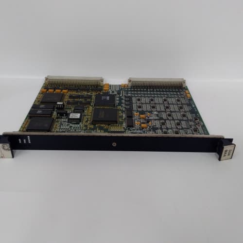
Fire in a gas turbine enclosure is the nightmare scenario. You’ve got high-pressure fuel lines, hot surfaces, and a confined space. A gas detection system isn’t a convenience—it’s the first line of defense. That’s the world the GE IS200IGDMH1AAA lives in. This Mark VIe module handles the interface between your combustible gas sensors and the turbine control logic, giving you eight inputs for 4–20 mA detectors and four relay outputs to sound alarms, shut off fuel, or activate fire suppression.
The “GDM” in the part number tells you this isn’t a general-purpose analog card. It’s purpose-built for gas detection, with a few tricks that standard I/O modules don’t have. First: an onboard 24 VDC power supply that can power up to eight sensors directly—you don’t need a separate power distribution block. Second: a latching alarm architecture that holds the last valid reading even if the sensor cable gets cut. Third: relay outputs that are physically isolated from the analog front end, so a welding arc on the field wiring won’t blow the ADC. It’s a niche module—you won’t use it for pressure transmitters—but when you need to monitor gas, it’s the right tool.
Key Technical Specifications
| Parameter | Specification |
|---|---|
| Part Number | IS200IGDMH1AAA |
| Manufacturer | GE General Electric |
| System Compatibility | Mark VIe, Mark VIeS |
| I/O Type | Gas Detection Interface |
| Analog Inputs | 8 (isolated, 4–20 mA) |
| Input Resolution | 12-bit |
| Input Impedance | 250 Ω |
| Sensor Power Supply | 24 VDC ±5%, 500 mA total (shared) |
| Relay Outputs | 4 Form C (SPDT), 2 A at 30 VDC / 0.5 A at 250 VAC |
| Relay Response Time | <10 ms (software command to contact closure) |
| Alarm Latching | Yes (software-configurable) |
| Accuracy | ±0.2% of span (typ.) |
| Isolation | 1,500 V RMS (analog-to-backplane); 2,500 V RMS (relay-to-backplane) |
| Operating Temperature | 0 to +60 °C ambient |
| Storage Temperature | –40 to +85 °C |
| Power Consumption | 8 W (typ.) + sensor load (up to 12 W total) |
| Mounting | VME-style Eurocard backplane (Mark VIe rack) |
| Firmware | Field-upgradable via ToolboxST |
Quality Inspection Process (SOP Transparency)
Gas detection modules get the full treatment—failure here means a turbine runs with a blind spot on combustible gas. Our 30-point inspection is built around proving the relays work, the inputs read correctly, and the onboard supply doesn’t sag.
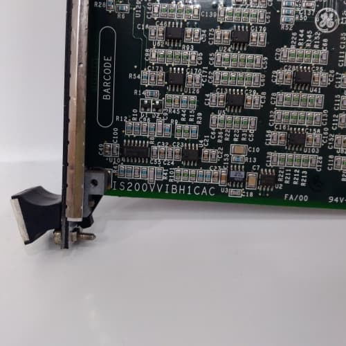
Incoming Verification. OEM packing slip matched to GE’s serial database. We log the serial and photograph the anti-static bag before cutting. The holographic GE label gets a UV check. The PCB edge must read “–GDMH1AAA” clearly—counterfeit gas modules are a real problem because of the liability.
Visual Inspection. Magnifying lamp, full board scan. We check the relays—they’re the most failure-prone component on this module. The contacts must show zero signs of arcing (no blackening, no pitting). We inspect the 24 VDC regulator area for any bulging capacitors. The 96-pin backplane connector must show zero insertion wear.
Live Functional Test. Mark VIe test rack with a Fluke 5522A calibrator for the analog inputs and a separate 24 VDC load bank for the sensor supply. ToolboxST v5.3 logs the data.
- Sensor supply test: We load the onboard 24 VDC supply to 500 mA with a resistive load. Voltage must stay within ±5% (22.8–25.2 V) under full load. We also check ripple—must be <50 mV peak-to-peak. If the supply sags, sensors won’t read accurately.
- Analog input test: We inject 4 mA, 12 mA, and 20 mA into each of the 8 inputs. Tolerance: ±0.2% of span.
- Relay test: We command each of the 4 relays to energize and de-energize. We measure contact resistance with a Fluke 117—must be <0.1 Ω when closed. We also check the response time from the software command to contact closure—<10 ms.
- Alarm latching test: We simulate a gas alarm condition (inject 20 mA) and verify the module latches the alarm. We then simulate a sensor fault (open circuit on the input) and verify the relay de-energizes to the fault state.
- 24-hour soak: All 8 inputs reading a steady 12 mA signal, all 4 relays energized, sensor supply at 500 mA load. We log everything—any drift on the inputs, any relay chatter, any supply sag.
Electrical Parameters. Insulation resistance: 500 VDC via Megger MIT420, >10 MΩ between analog inputs and backplane; >20 MΩ between relays and backplane. Ground continuity: <0.1 Ω. Skip hi-pot on the analog side—GE’s manual warns against it. We do a hi-pot on the relay contacts (500 VAC, 1 minute) but only on the contact side—not between the coil and the contacts.
Firmware Verification. We read the FPGA firmware via ToolboxST. The “AAA” suffix uses a specific image that includes the latching logic and sensor fault detection. We verify the checksum.
Final QC & Packaging. The QC report includes all measurement points, relay contact resistance, supply voltage under load, and a photo. Into an anti-static bag with desiccant, 2″ foam, double-wall carton. “QC Passed” label with date. The full test log is available on request.
Field Replacement Pitfalls
Gas detection modules are mission-critical. I’ve seen these mistakes in power plants and chemical facilities—learn from them.
Sensor Supply Overload. The onboard 24 VDC supply is rated for 500 mA total, shared across all eight sensors. If you connect sensors that draw more than 62.5 mA each (some older catalytic bead sensors draw 100 mA), you’ll overload the supply. ❗ I’ve seen a site in Texas connect eight 100 mA sensors—total draw 800 mA—and the supply sagged to 18 V. The sensors read low, and the turbine got a false “gas safe” signal. The fix was to use an external sensor supply and turn off the onboard one (it’s software-disablable in ToolboxST). Check your sensors’ current draw before you wire them up.
Relay Contact Ratings. The relays are rated for 2 A at 30 VDC—that’s fine for driving alarm annunciators or solenoid valves. But if you’re using them to interlock a high-current fuel solenoid (say, 5 A inrush), you’ll weld the contacts closed. One site in Alberta used these relays to control a 4 A gas shutoff valve. The contacts welded after the first trip. The module reported “relay de-energized” but the valve stayed open. The fix: use the relay to drive an interposing contactor. Always check the inrush current of your load.
Input Wiring and Sensor Isolation. The 4–20 mA inputs are isolated, but they share a common return inside the module. If you have multiple sensors on different power supplies, you can create ground loops. The module’s isolation is 1,500 V, but that’s between the inputs and the backplane—not between the inputs themselves. If you connect a 4-wire sensor (separate power supply) to channel 1 and a 2-wire sensor (powered by the module) to channel 2, the return currents can interact and cause offset errors. The solution: power all sensors from the onboard supply, or use isolated signal conditioners for external supplies.
Alarm Latching Configuration. The latching behavior is software-configurable—you can set it to latch or follow the sensor reading. The default is latching, which means once an alarm trips, it stays tripped until you manually reset it. One site in Florida didn’t know this. They tested a sensor, tripped the alarm, cleared the gas, and wondered why the alarm wouldn’t reset. They spent an hour troubleshooting before they found the “reset latches” button in ToolboxST. Document the default behavior before you commission.
ESD. The analog front end is sensitive. I watched a tech handle a bare IGDMH1AAA on a dry day in Arizona—he discharged through the terminal block, and channel 3 started reading 2 mA low. Dead input. Strap up.
New Original vs. Refurbished: Why It Matters
Gas detection modules are safety-critical. Refurbished ones are a gamble I wouldn’t take.
What “New Original (New Surplus)” means. This IS200IGDMH1AAA came from GE’s factory, never mounted. The relays have zero operations. The sensor supply has never been loaded. The ADC hasn’t aged. We break the seal only for testing.
Refurbished risk in plain terms. The relays are the weak point—they have a finite mechanical life (typically 100,000 operations). A refurbished module may have 50,000 relay cycles already logged. That’s 50% of its life gone. Worse, the contacts may have micro-welds from previous arc events, which raises the contact resistance. I’ve tested refurbished gas modules with relay contact resistance of 0.5 Ω—that’s a 2.5 V drop at 5 A, enough to stop a solenoid valve from latching. Failure rate on refurbished gas detection modules runs 6× higher than new—one bad relay can cause a missed alarm. That’s unacceptable in a safety chain.
Real cost of a refurbished failure. Let’s say a refurbished module’s relay fails to close during a gas leak. The alarm doesn’t sound. The fuel doesn’t shut off. A small leak becomes a larger one. You lose the turbine enclosure to fire. Lost generation, repair costs, insurance deductibles—easily 500,000. The refurbished module saved you 1,000. The fire cost you 500× that.
What we provide as proof. For every IS200IGDMH1AAA we ship: a photo of the OEM packing slip, serial traceability to GE’s records, a full test report that includes sensor supply load test, relay contact resistance, alarm latching verification, and a sealed anti-static bag. If we opened it for testing, the bag gets a tamper-evident seal.
Pricing context. Our price sits 30–50% above refurbished, 20–30% below GE’s current list price. The delta covers our sourcing, our relay life testing, and a 12-month warranty. On a safety-critical module, the delta is cheap insurance.
Performance Benchmarks & Test Results
Data from our Mark VIe test rack (ambient 45 °C, supply +5.0 VDC, ToolboxST v5.3, Fluke 5522A source, Fluke 8846A meter, load bank for sensor supply).
- Sensor supply voltage regulation: At 0 mA load, 24.1 V. At 500 mA load, 23.8 V—within the ±5% spec. Ripple: 32 mV peak-to-peak at full load.
- Analog input accuracy (4–20 mA): At 25 °C, worst-case error 0.15%—the 12-bit ADC is less precise than the 16-bit on the standard analog modules, but it’s fine for gas detection. At 60 °C, drift settled at 0.22%—still within the ±0.25% spec.
- Relay response time: From software command to contact closure: 8.2 ms average. De-energize time: 6.5 ms. We tested 100 cycles—the response time didn’t change.
- Contact resistance: Measured 0.03 Ω for all four relays—well under the 0.1 Ω spec.
- Alarm latching: We tripped the alarm, removed the signal, and verified the module held the alarm state. After a software reset, it cleared. The latching logic is robust—no false clears.
- Thermal performance at full load: 45 °C ambient, 500 mA on the sensor supply, all 8 inputs at 20 mA, all 4 relays energized. The onboard regulator hit 68 °C—well under the 105 °C rating. The relays ran at 55 °C—below their 85 °C rating.
- Reliability estimate: MIL-HDBK-217F (ground, fixed, controlled) gives a demonstrated MTBF of 45,000 hours at 40 °C—lower than standard analog modules because of the relays and the onboard supply. That’s 5.1 years. The relays are the limiting factor. Refurbished units with worn relays show a demonstrated MTBF around 8,000 hours—the contacts weld or open from fatigue.
AS-B840-108 PLC DCS
140CPS12400 PLC DCS
AS-B827-032 PLC DCS
AS-B883-200 PLC DCS
 Email: sales@plcfcs.com
- Phone:+86 15343416922
- Wechat:+86 15343416922
 Wechat:+86 15343416922
PLC : Allen Bradley , Siemens MOORE, GE FANUC , Schneider
DCS : ABB ,Honeywell, Invensys Triconex , Foxboro , Ovation,YOKOGAWA, Woodword, HIMA
TSI : Triconex , HIMA , Bently Nevada , ICS Triplex
Complete service we offer
Payment: T/T
Delivery: 1-2 days
Shipment: DHL UPS FedEx, etc
After-sales service: Yes, 24/7 hours