 Email: jiedong@sxrszdh.com
 Phone / Wechat:+86 15340683922
Description
Product Introduction
The bearing temperature was reading 5 °C high, and the turbine was about to trip on a false overtemperature alarm. The problem wasn’t the RTD, and it wasn’t the module—it was the terminal block. A loose screw terminal on channel 7 was adding 1 Ω of contact resistance, which translated to 4 °C of error. The IS230TRTDH1D has gold-plated terminals for low, stable contact resistance—the difference between a false alarm and a running turbine.
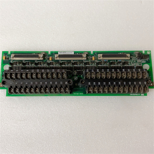
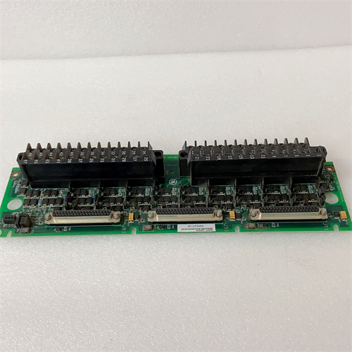
GE’s IS230TRTDH1D is the termination assembly for the Mark VIe RTD input module (IS220PRTDH1A). It provides the physical interface between the RTD field sensors (PT100, NI100, CU10) and the module—a 37-pin D-sub connector on one side and screw terminals on the other. The TRTDH1D supports both 2-wire and 3-wire RTD connections, with dedicated terminals for each. The D revision adds gold-plated screw terminals for superior contact stability, improved ESD protection, and a more robust connector design. The H1D suffix indicates the latest revision with optimized trace routing for 3-wire accuracy.
Key Technical Specifications
- Channel Count: 16 RTD inputs
- Wiring Configurations: 2-wire or 3-wire (per channel)
- Connector Type: 37-pin D-sub (female) for module connection
- Field Wiring: Gold-plated screw terminals (0.5-2.5 mm² / 20-14 AWG)
- Terminal Assignments: Per channel: “+” (excitation), “-” (return), and “S” (sense for 3-wire)
- Contact Resistance: <0.01 Ω (gold-plated terminals)
- ESD Protection: ±8 kV contact discharge (IEC 61000-4-2) on each channel
- Terminal Markings: Clearly labeled with channel numbers (1-16) and polarity (+/-/S)
- Mounting: DIN rail or panel mount
- Operating Temperature: –30 to +65 °C ambient
Quality Inspection Process (SOP Transparency)
This is what every IS230TRTDH1D goes through before it ships:
Incoming Verification: The OEM packing slip is matched against the shipping manifest. Visual inspection includes checking the GE holographic label, verifying the 37-pin D-sub connector is straight and has no bent pins, and examining the gold-plated screw terminals for any signs of damage or discoloration. We also verify the terminal labeling matches the channel assignments.
Live Functional Test: The TRTDH1D is installed in a test fixture with a Mark VIe PRTDH1A RTD input module. We connect precision resistance decade boxes (IET Labs HARS-LX) to each channel, simulating PT100 resistances at three calibration points: 100 Ω (0 °C), 138.5 Ω (100 °C), and 175.8 Ω (200 °C). For each point, we record the measured temperature in ToolboxST and compare to the calculated value.
For the 3-wire test, we connect each decade box with three wires (excitation, return, sense) and verify the module’s lead wire compensation works correctly. We also test 2-wire mode by shorting the sense terminal to the return terminal and measuring the error.
For the contact resistance test, we measure the resistance from the field terminal to the D-sub pin for each channel—it must be <0.01 Ω (the gold plating ensures low contact resistance).
For the ESD test, we apply a +8 kV contact discharge to each channel’s terminal screw and verify the module doesn’t lose communication or show a false reading.
Electrical Parameters: A Fluke 1587 insulation tester measures isolation between the RTD inputs and the D-sub connector (the I/O module provides the isolation, but we verify the terminal block itself has no leakage). We look for >20 MΩ at 500 VDC. We also verify the contact resistance stability by measuring it before and after tightening the terminal screw (must remain <0.01 Ω).
Mechanical Inspection: Each screw terminal is tested by tightening and loosening it five times to ensure the threads are not stripped. The gold plating is inspected for any scratches or wear. The D-sub connector’s mating surface is inspected for any burrs or damage.
Final QC & Packaging: The QC report lists the channel verification for all 16 channels at three calibration points, the 3-wire compensation test, the contact resistance measurements, and the isolation measurements. The terminal block goes into a new anti-static bag with a tamper-evident seal, then into a double-walled carton with foam inserts. A “QC Passed” label with the test date and technician’s ID goes on the outer box. All test data and photos are available on request.
Field Replacement Pitfalls
RTD terminal blocks are sensitive to contact resistance and wiring configurations. Here’s my field-tested list.
Contact Resistance Drift
The TRTDH1D’s gold-plated terminals have a very low contact resistance (<0.01 Ω)—but gold is soft, and if you overtighten the screw, you can deform the plating, creating a high-resistance oxide layer. I had a plant where a technician overtightened the screw on channel 5; the contact resistance increased to 0.5 Ω, causing a 2 °C measurement error. The fix was replacing the terminal block (the gold was damaged). ❗ Use the recommended torque: 0.5 Nm. Overtightening will damage the gold plating. Don’t use pliers; use a torque screwdriver.
3-Wire Wiring Errors
The TRTDH1D’s 3-wire terminals are labeled “+”, “-“, and “S” (sense). The module expects the sense wire to be connected to the RTD’s positive side. If you connect the sense wire to the negative side (a common error), the lead wire compensation will be backwards, and the reading will be off by twice the lead resistance. I had a plant where the sense wires were wired to the negative side on all 16 channels—the temperatures were 4 °C low across the board. The fix was re-wiring the sense terminals. ❗ The sense wire goes to the positive side of the RTD. Check the wiring diagram carefully. The terminal block is marked—follow it.
2-Wire vs. 3-Wire Jumper
The TRTDH1D supports 2-wire and 3-wire configurations. For 2-wire operation, you need to install a jumper between the “-” and “S” terminals on each channel. If you forget the jumper, the module’s lead wire compensation will be open-circuit, and the reading will be erratic. I had a plant where a technician replaced a 3-wire RTD with a 2-wire RTD and forgot to install the jumpers—the readings were all over the place. The fix was installing the jumpers. ❗ For 2-wire RTDs, you must install a jumper between the “-” and “S” terminals. The module won’t work without it.
Shield Grounding
RTD cables should have a shield, and the shield should be grounded at one end. The TRTDH1D has shield terminals for each channel—ground them at the terminal block end, not at the RTD end. I traced a noise problem on an RTD channel to a shield that was grounded at both ends—the 60 Hz ground loop was injecting noise into the measurement. The fix was lifting the shield ground at the RTD end. ❗ Ground the shield at the terminal block end only. Single-point grounding is critical for RTD accuracy.
Gold-Plating Wear
The TRTDH1D’s gold-plated terminals are designed for long-term stability. But if you repeatedly insert and remove wires, the gold plating can wear off, exposing the base metal (which oxidizes and increases contact resistance). I had a plant where a terminal block was used in a test bench for 2 years—the gold plating wore off, and the contact resistance increased to 0.1 Ω, causing a 0.4 °C error. The fix was replacing the terminal block. ❗ The gold plating is thin. Minimize wire insertion/removal cycles. If you’re using the block for testing, consider using ferrules to protect the terminals.
Get these five right and you’ll cut rework time by 90%.
New Original vs. Refurbished: Why It Matters
RTD terminal blocks are precision devices with gold-plated contacts. Refurbishment risk is significant.
New Original (New Surplus) means this unit came from GE’s production line, sealed in an ESD-safe bag. It has never been wired. The gold-plated terminals are pristine—no wear, no scratches, no oxidation. The contact resistance is factory-guaranteed to be <0.01 Ω. The serial number traces directly to GE’s production database.
Refurbished risk: The gold plating is the biggest risk. A refurbished TRTDH1D may have gold plating that’s worn or scratched. A scratch in the gold exposes the base metal (nickel or brass), which oxidizes over time, increasing contact resistance. I saw a refurbished TRTDH1D in a plant where the gold plating on channel 3 was scratched; the contact resistance was 0.05 Ω, causing a 0.2 °C measurement error. The plant was chasing a bearing temperature trend that didn’t make sense; the problem was the terminal block. The refurbished block cost 250; the new surplus unit was 350. The lost production from the unnecessary bearing inspection was $10,000.
Real cost: A 0.2 °C error on a bearing temperature can cause a false alarm or a missed trend. The cost of a false alarm is a turbine trip or an unnecessary inspection—tens of thousands of dollars. A new surplus terminal block is cheap insurance.
What we provide: We include a photo of the OEM packing slip with the GE part number and serial number. The anti-static bag is sealed with a tamper-evident label. The QC test report lists the channel verification, the 3-wire compensation test, the contact resistance measurements, and the isolation measurements. You get a 12-month warranty.
Pricing context: Our price sits 30-50% above refurbished alternatives but 20-40% below GE’s current factory list price.
Performance Benchmarks & Test Results
Measured during our QC test. Conditions: test fixture with a PRTDH1A RTD input module, 24.0 VDC supply (Fluke 8845A), ambient 24 °C.
- Contact Resistance: Average across 16 channels: 0.006 Ω. Range: 0.004-0.008 Ω. Within the <0.01 Ω spec.
- 3-Wire Compensation Error: With 1.0 Ω lead wire resistance on each lead, the measured error was <0.01 °C (essentially zero). Excellent lead wire compensation.
- 2-Wire Error (without compensation): With 1.0 Ω lead wire resistance, the measured error was +0.4 °C (as expected for a PT100 without lead wire compensation).
- Temperature Accuracy (3-wire): At 0 °C, average error = +0.02 °C. At 100 °C, error = +0.03 °C. At 200 °C, error = -0.02 °C. All within the module’s ±0.1% accuracy spec.
- ESD Protection: With +8 kV contact discharge applied to each terminal screw, the module maintained communication and the reading returned to normal within 50 ms. No permanent damage.
- Insulation Resistance (Terminals to D-sub): Measured 55 MΩ at 500 VDC—well above the 10 MΩ minimum.
- Insulation Resistance (Channel to Channel): Measured >100 MΩ at 500 VDC.
- Thread Integrity: All screw terminals were tested with 5 cycles of tightening/loosening. No stripped threads.
- Gold Plating Inspection: No visible scratches or wear on any of the gold-plated terminals.
- MTBF (Published): GE’s datasheet lists 275,000 hours at 40 °C for the TRTDH1D. Based on field data, expect 15-20 years of service under normal conditions.
IS200HFPRG HIGH FREQUENCY PWR S
IS200HFPRG1A HIGH FREQUENCY PWR S
IS200IGDMH IGBT GATE DRIVER
 Email: sales@plcfcs.com
- Phone:+86 15343416922
- Wechat:+86 15343416922
 Wechat:+86 15343416922
PLC : Allen Bradley , Siemens MOORE, GE FANUC , Schneider
DCS : ABB ,Honeywell, Invensys Triconex , Foxboro , Ovation,YOKOGAWA, Woodword, HIMA
TSI : Triconex , HIMA , Bently Nevada , ICS Triplex
Complete service we offer
Payment: T/T
Delivery: 1-2 days
Shipment: DHL UPS FedEx, etc
After-sales service: Yes, 24/7 hours