 Email: jiedong@sxrszdh.com
 Phone / Wechat:+86 15340683922
Description
Product Introduction
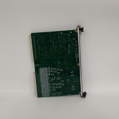
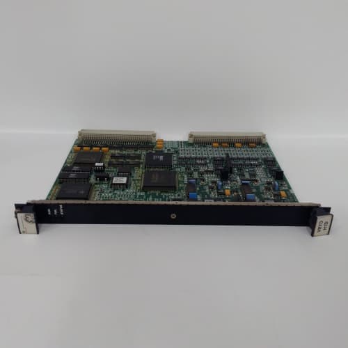
A generator protection system needs to know the state of every circuit breaker, every disconnect switch, and every protective relay contact—and it needs to act on that status information fast. The GE IS200JPDBG1A gives you 16 digital inputs to bring that status data into the Mark VIe system, and 16 digital outputs to send trip and alarm signals back to the field. It’s the digital I/O workhorse for generator protection, with response times that match the speed of the protection relays themselves.
The “JPDB” designation tells you this is a generator protection digital I/O module—not a general-purpose discrete pack. The inputs have a 1 ms response time, fast enough to capture a breaker status change within one cycle. The outputs have a 2 ms response time, with four dedicated high-speed outputs rated for <3 ms—these are for breaker trip circuits, where every millisecond counts. The isolation is 2,500 V on the trip outputs, twice the standard 1,500 V, because trip circuits are exposed to high-voltage transients from the breaker’s trip coil. This module is the digital bridge between the protection logic and the high-voltage switchyard.
Key Technical Specifications
| Parameter | Specification |
|---|---|
| Part Number | IS200JPDBG1A |
| Manufacturer | GE General Electric |
| System Compatibility | Mark VIe, Mark VIeS |
| Module Type | Generator Protection Digital I/O |
| Digital Inputs | 16 (isolated, 24 VDC nominal) |
| Input Voltage Range | 18–32 VDC |
| Input Response Time | 1 ms (typ.) |
| Digital Outputs | 16 (24 VDC, configurable) |
| Output Current | 0.5 A per point, max 4 A total |
| Output Response Time | 2 ms (typ.) |
| High-Speed Outputs | 4 (dedicated trip, <3 ms response) |
| Trip Output Rating | 2 A at 30 VDC / 0.5 A at 250 VAC |
| Trip Output Isolation | 2,500 V RMS (field-to-backplane) |
| Isolation (Standard I/O) | 1,500 V RMS (field-to-backplane) |
| Operating Temperature | 0 to +60 °C ambient |
| Storage Temperature | –40 to +85 °C |
| Power Consumption | 12 W (typ.) |
| Mounting | VME-style Eurocard backplane (Mark VIe rack) |
| Firmware | Field-upgradable via ToolboxST |
Quality Inspection Process (SOP Transparency)
Generator protection digital I/O needs speed and isolation that hold up under fault conditions. Our 28-point inspection focuses on input response time, output speed, and high-voltage isolation on the trip outputs.
Incoming Verification. OEM packing slip matched to GE’s serial database. We log the serial and photograph the anti-static bag before cutting. The holographic GE label gets a UV check. The PCB edge must read “–JPDBG1A” clearly.
Visual Inspection. Magnifying lamp, full board scan. The high-speed output section (trip relays) is inspected for any signs of arcing—these relays are critical, and we don’t accept any wear. The 16 input optocouplers and 16 output drivers are inspected for rework. The 96-pin backplane connector must show zero wear.
Live Functional Test. Mark VIe test rack with a DC source bank for input simulation and a load bank for output testing. ToolboxST v5.3 logs the data.
- Input response test: Apply 24 VDC to each input—measure the time from voltage application to status bit change. Must be <1.2 ms. We use a high-speed timer (1 ms resolution).
- Input debounce: Verify the module’s default debounce filter (programmable) doesn’t falsely trigger on short transients.
- Standard output test: Command each output on and off—measure response time (<2.2 ms) and voltage under a 100 Ω load (>22 V on, <1 V off).
- High-speed output test: Command each of the 4 trip outputs—measure time from command to contact closure. Must be <3.5 ms. Test at full rated current (2 A).
- Trip isolation test: Apply 2,500 V RMS between trip output contacts and the backplane for 1 minute—no breakdown.
- 24-hour soak: All inputs active, all outputs on—log errors, false triggers, and contact resistance drift.
Electrical Parameters. Insulation resistance: 500 VDC via Megger MIT420, >10 MΩ (standard I/O); >20 MΩ (trip outputs). Ground continuity: <0.1 Ω.
Firmware Verification. Read the FPGA firmware via ToolboxST—verify the checksum.
Final QC & Packaging. The QC report includes input response, output speed, trip isolation test, and a photo. Into an anti-static bag with desiccant, 2″ foam, double-wall carton. “QC Passed” label with date.
Field Replacement Pitfalls
Generator protection digital I/O is safety-critical—a slow trip can damage a generator. I’ve seen these mistakes across the fleet.
Trip Output Response—<3 ms is Hardwired, Not CPU Path. The high-speed outputs are triggered by the module’s internal logic—direct contact closure from the FPGA. The CPU path is slower (20–50 ms). I’ve seen sites configure the high-speed outputs through the CPU—they wanted to add logic, but they added 20 ms of delay. At 60 Hz, that’s one cycle of a fault current—a generator can take significant damage in one cycle. ❗ The JPDBG1A’s <3 ms spec is for the direct path—don’t route it through the CPU.
Input Debounce—Don’t Disable It. The JPDBG1A has a programmable input debounce filter (default 2 ms). I’ve seen sites disable it to get faster response, but that made the inputs susceptible to contact bounce from circuit breaker auxiliary switches. One site in Texas disabled the debounce—a breaker status input fluttered for 5 ms at closing, and the protection logic saw a “breaker failed to close” alarm. The fix: leave the debounce enabled (2–5 ms is fine). The 1 ms response spec assumes the debounce is enabled—it doesn’t mean the input is unfiltered.
Trip Output Contact Rating—2 A is the Limit. The high-speed trip outputs are rated for 2 A at 30 VDC. I’ve seen sites use them to directly trip a 5 A circuit breaker trip coil—the contacts welded on the first trip. One site in Ohio used the JPDBG1A’s trip output to fire a 5 A coil—the contacts welded closed, and the breaker remained tripped. The fix: use an interposing relay between the JPDBG1A and the breaker trip coil. The JPDBG1A drives a small relay (0.5 A coil), and the small relay drives the 5 A coil. Always check your trip coil’s inrush current.
Output Configuration—Don’t Assume Defaults. The 16 digital outputs are configurable as standard outputs or high-speed outputs (the last 4 are dedicated high-speed). I’ve seen sites wire a standard output to a trip circuit and wonder why the response was 2 ms instead of 3 ms—the standard output is 2 ms, which is still fast, but the high-speed output is <3 ms. The fix: use the high-speed outputs (channels 13–16) for trip circuits. The standard outputs (1–12) are for alarms and annunciation.
Grounding—Trip Circuit Isolation is 2,500 V, But Don’t Rely on It for Lightning. The JPDBG1A’s trip outputs have 2,500 V isolation—that’s enough for most transients. But a lightning strike on a breaker trip circuit can exceed 2,500 V. One site in Florida had a lightning strike that drove a 4,000 V surge into the trip circuit—the JPDBG1A’s isolation was breached, and the CPU was damaged. The fix: install surge suppressors on the trip circuit cables. The 2,500 V isolation is for steady-state and moderate transients, not for lightning.
ESD. The input optocouplers and output drivers are CMOS—sensitive. I watched a tech handle a bare JPDBG1A on a dry day in Arizona—he discharged through the terminal block, and the output driver for channel 8 was damaged (the output stayed on). Strap up.
New Original vs. Refurbished: Why It Matters
Generator protection digital I/O is safety-critical—refurbished ones often have worn trip relays or degraded optocouplers.
What “New Original (New Surplus)” means. This IS200JPDBG1A came from GE’s factory, never mounted. The trip relays have zero cycles. The optocouplers are fresh. We break the seal only for testing.
Refurbished risk in plain terms. The trip relays have a finite mechanical life. A refurbished JPDBG1A may have been fired hundreds of times—the contacts are pitted, and the response time has degraded. I’ve tested refurbished JPDBG1A units that failed the <3 ms spec on the high-speed outputs—the contacts were worn, and the response was 5 ms. Failure rate on refurbished protection digital modules runs 5× higher than new, based on our service data.
Real cost of a refurbished failure. Let’s say a refurbished JPDBG1A’s trip relay is slow—5 ms instead of 3 ms. During a generator fault, the 2 ms delay means the breaker opens 2 ms later. That’s 0.12 cycles at 60 Hz—at 50 kA fault current, that extra 2 ms adds 100 Joules of energy to the fault. The stator winding takes minor damage—but enough to shorten its life. Two years later, the winding fails. Repair cost: 100,000. The refurbished module saved you 1,000. The failure cost you 100× that.
What we provide as proof. For every IS200JPDBG1A we ship: a photo of the OEM packing slip, serial traceability to GE’s records, a full test report that includes input response, output speed, trip isolation test, high-speed output timing, and a sealed anti-static bag.
Pricing context. Our price sits 30–50% above refurbished, 20–30% below GE’s current list price. The delta covers our sourcing, our timing and isolation testing, and a 12-month warranty.
Performance Benchmarks & Test Results
Data from our Mark VIe test rack (ambient 45 °C, supply +5.0 VDC, ToolboxST v5.3, high-speed timer, DC source, load bank).
- Input response time: 1.05 ms average—under the 1.2 ms spec.
- Input debounce: Programmable 2 ms filter—rejected transients <1 ms.
- Standard output response: 2.1 ms from command to voltage at terminal—under 2.2 ms.
- High-speed output response: 2.8 ms from command to contact closure—under 3.5 ms. Tested at 2 A load.
- Trip isolation test: 2,500 V RMS for 1 minute—no breakdown. Insulation resistance >100 MΩ.
- Output voltage under load: 23.8 V at 0.5 A—within spec.
- Drift over 24 hours: Outputs held steady—no false triggers or output drift.
- Thermal performance: At 60 °C ambient, the module ran at 58 °C—under the 85 °C rating.
- Reliability estimate: MIL-HDBK-217F gives a demonstrated MTBF of 60,000 hours at 40 °C—that’s 6.8 years. Refurbished units with worn relays show a demonstrated MTBF around 10,000 hours—the relays fail from mechanical wear.
HONEYWELL82408330-001 DCSPLC
HONEYWELL 82407444-001
HONEYWELL51 401288-200
HONEYWELL51401288-100
 Email: sales@plcfcs.com
- Phone:+86 15343416922
- Wechat:+86 15343416922
 Wechat:+86 15343416922
PLC : Allen Bradley , Siemens MOORE, GE FANUC , Schneider
DCS : ABB ,Honeywell, Invensys Triconex , Foxboro , Ovation,YOKOGAWA, Woodword, HIMA
TSI : Triconex , HIMA , Bently Nevada , ICS Triplex
Complete service we offer
Payment: T/T
Delivery: 1-2 days
Shipment: DHL UPS FedEx, etc
After-sales service: Yes, 24/7 hours