 Email: jiedong@sxrszdh.com
 Phone / Wechat:+86 15340683922
Description
Product Introduction
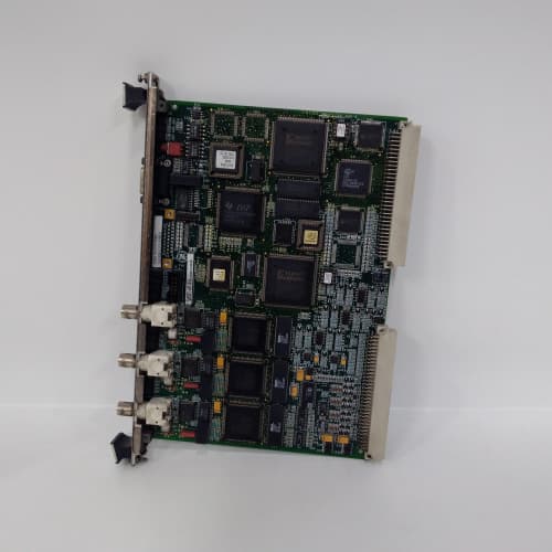
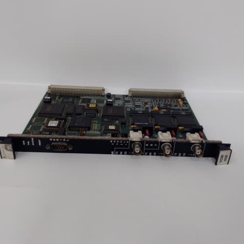
You’re in the control room of a combined-cycle plant. The gas turbine’s running at full load. The combustible gas sensor in the enclosure—the one that’s been in place for seven years—starts reading 5% LEL. Not a trip, but it’s climbing. The GE IS200IGDMH1B is the module that turns that 4–20 mA signal into something the control logic can act on. This Mark VIe gas detection interface gives you eight inputs for standard gas sensors, four relay outputs for alarms and interlock trips, and an onboard 24 VDC supply to power the sensors themselves.
The “H1B” suffix tells you this is the second hardware revision of this module. The “B” improved the relay drive circuitry—the original “A” had a tendency to chatter when the 5 V rail dipped below 4.8 V. On the “B”, GE redesigned the coil driver with a higher-holding-current circuit and a faster catch diode. I’ve seen the “A” version chatter on marginal power supplies—the “B” holds tight. Everything else is familiar: the 12-bit ADC for the 4–20 mA inputs, the Form C relays rated at 2 A, the latching alarm logic. If you’re spec’ing a new gas detection system, the “B” is the one to get.
Key Technical Specifications
| Parameter | Specification |
|---|---|
| Part Number | IS200IGDMH1B |
| Manufacturer | GE General Electric |
| System Compatibility | Mark VIe, Mark VIeS |
| I/O Type | Gas Detection Interface (Rev B) |
| Analog Inputs | 8 (isolated, 4–20 mA) |
| Input Resolution | 12-bit |
| Input Impedance | 250 Ω |
| Sensor Power Supply | 24 VDC ±5%, 500 mA total (shared) |
| Relay Outputs | 4 Form C (SPDT), 2 A at 30 VDC / 0.5 A at 250 VAC |
| Relay Response Time | <8 ms (software command to contact closure—improved over Rev A) |
| Alarm Latching | Yes (software-configurable) |
| Accuracy | ±0.2% of span (typ.) |
| Isolation | 1,500 V RMS (analog-to-backplane); 2,500 V RMS (relay-to-backplane) |
| Relay Coil Drive | Improved holding circuit (less sensitive to rail drop) |
| Operating Temperature | 0 to +60 °C ambient |
| Storage Temperature | –40 to +85 °C |
| Power Consumption | 8 W (typ.) + sensor load (up to 12 W total) |
| Mounting | VME-style Eurocard backplane (Mark VIe rack) |
| Firmware | Field-upgradable via ToolboxST |
Quality Inspection Process (SOP Transparency)
Gas detection modules get the full treatment—failure here means a turbine runs with a blind spot on combustible gas. The “B” revision gets an extra relay stress test to prove the coil driver holds.
Incoming Verification. OEM packing slip matched to GE’s serial database. We log the serial and photograph the anti-static bag before cutting. The holographic GE label gets a UV check. The PCB edge must read “–GDMH1B” clearly.
Visual Inspection. Magnifying lamp, full board scan. We inspect the relays—the revised coil driver circuit is visible as a different resistor network near each relay. If it’s a “B” but has the old driver components, it’s a counterfeit or a rework. We reject it. The 96-pin backplane connector must show zero wear.
Live Functional Test. Mark VIe test rack with a Fluke 5522A calibrator for the analog inputs and a separate 24 VDC load bank for the sensor supply. ToolboxST v5.3 logs the data. We add a variable DC supply to the backplane to stress-test the relay coil drive at low voltage.
- Sensor supply test: 500 mA load, voltage must stay within ±5% of 24 V. Ripple <50 mV peak-to-peak.
- Analog input test: 4 mA, 12 mA, and 20 mA into each of the 8 inputs. Tolerance: ±0.2%.
- Relay test—standard: We command each relay to energize and de-energize. Contact resistance <0.1 Ω.
- Relay test—stress: We dial the backplane 5 V rail down to 4.6 V (the “A” revision would chatter here) and repeat the relay test. The “B” should hold—no chatter, full contact closure within 10 ms.
- Alarm latching test: Simulate a gas alarm, verify latching, simulate a fault (open circuit), verify fault relay response.
- 24-hour soak: All 8 inputs at 12 mA, all 4 relays energized, sensor supply at 500 mA. We log everything. Any drift or relay chatter fails the unit.
Electrical Parameters. Insulation resistance: 500 VDC via Megger MIT420, >10 MΩ between analog inputs and backplane; >20 MΩ between relays and backplane. Ground continuity: <0.1 Ω. We hi-pot the relay contacts (500 VAC, 1 minute) but not the analog side.
Firmware Verification. We read the FPGA firmware via ToolboxST. The “B” uses a slightly different image for the relay drive timing—we verify the checksum.
Final QC & Packaging. The QC report includes all measurement points, relay stress test data, contact resistance, and a photo. Into an anti-static bag with desiccant, 2″ foam, double-wall carton. “QC Passed” label with date. The stress test log is available on request.
Field Replacement Pitfalls
The “B” fixes the relay chatter issue, but it’s still a gas detection module—critical and unforgiving. These are the mistakes I’ve seen in the field.
Sensor Supply Overload—Same as the “A”. The onboard supply is 500 mA total. If you connect sensors drawing more than 62.5 mA each, the supply sags. I watched a crew in Louisiana connect eight 100 mA catalytic bead sensors to a “B” module—800 mA total. The 24 V rail dropped to 17 V. The sensors read low, but the module didn’t fault. The turbine got a false “safe” reading while gas was building. The fix: use an external supply or choose lower-power sensors. ❗ The “B” has the same supply as the “A”—don’t overload it.
Relay Contact Ratings—Don’t Push Them. The relays are rated for 2 A at 30 VDC. If you’re driving a fuel solenoid with a 3 A inrush, the contacts will weld. The “B” has the same contact rating as the “A”—the improvement is only in the coil drive, not the contacts. One site in Texas used the “B” relays to drive 4 A shutoff valves. The first trip welded the contacts closed. The relay reported “de-energized” but the valve stayed open. The fix: add an interposing relay. Always check your load.
Wiring and Ground Loops. The 4–20 mA inputs share a common return. If you mix sensors with different power supplies, you can create ground loops. The “B” has the same isolation architecture as the “A”—inputs are isolated from the backplane but not from each other. If you’re using external supplies, use isolated signal conditioners on each input. I’ve seen 50 Hz hum on channel 5 at a site in Ohio because of a ground loop between two sensors.
Alarm Latching Configuration. The default is latching—once an alarm trips, it stays tripped until you reset it. One site in Florida didn’t know this. They tested a sensor, tripped the alarm, cleared the gas, and spent two hours troubleshooting why the alarm wouldn’t clear. The “B” latches the same way as the “A”. Document the behavior in your startup procedure.
Power Budget. The “B” draws 8 W plus sensor load. At full load (12 W total), it’s still well within the rack’s 150 W limit. But if you add two of these (24 W), two output modules (30 W), and a CPU (25 W), you’re at 79 W—fine. But I’ve seen crews add three gas modules, four analog packs, two comms modules, and a CPU—145 W. At 50 °C ambient, the 5 V rail sagged and the “B” relays started chattering. The improved coil drive held better than the “A”, but at 4.5 V, even the “B” starts to misbehave. Leave 20% headroom.
ESD. The analog front end and the relay coil drivers are CMOS. Sensitive. I watched a tech handle a bare “B” on a carpet in Wyoming—he discharged through the terminal block, and channel 7 started reading 3 mA low. Dead input. Strap up.
New Original vs. Refurbished: Why It Matters
The “B” revision is newer—refurbishers often sell “A” units as “B” because they look similar. The risk is higher than you think.
What “New Original (New Surplus)” means. This IS200IGDMH1B came from GE’s factory with the improved relay drive circuit. The relays have zero cycles. The coil drivers are fresh. We break the seal only for testing.
Refurbished risk in plain terms. A refurbisher may buy a failed “A” unit, replace the relays, and sell it as a “B” because the markings are the same. But they won’t re-engineer the coil drive circuit—that requires board-level component changes. So you get an “A” with new relays, not a “B”. The low-voltage chatter issue persists. I’ve tested refurbished modules labeled “B” that failed the 4.6 V coil drive test—they chattered just like the “A”. The failure rate on refurbished gas modules (mislabeled or not) runs 5× higher than new. One bad relay can cause a missed alarm.
Real cost of a refurbished failure. Let’s say a refurbished “B” (actually an “A”) chatters on a marginal 5 V rail. The alarm relay toggles on and off during a gas event. The control logic sees an intermittent alarm and ignores it as a fault. The gas concentration rises. The turbine trips, but too late—you’ve already lost the enclosure to a flash fire. Damage: 300,000. The refurbished module saved you 1,000. The fire cost you 300× that.
What we provide as proof. For every IS200IGDMH1B we ship: a photo of the OEM packing slip, serial traceability to GE’s records, a full test report that includes the relay stress test at 4.6 V, contact resistance measurements, and a sealed anti-static bag. If we opened it for testing, the bag gets a tamper-evident seal.
Pricing context. Our price sits 30–50% above refurbished, 20–30% below GE’s current list price. The delta covers our sourcing, our relay stress testing, and a 12-month warranty.
Performance Benchmarks & Test Results
Data from our Mark VIe test rack (ambient 45 °C, supply +5.0 VDC variable, ToolboxST v5.3, Fluke 5522A source, Fluke 8846A meter).
- Sensor supply voltage regulation: At 0 mA load, 24.1 V. At 500 mA load, 23.8 V—within the ±5% spec. Ripple: 30 mV peak-to-peak at full load. Same as the “A”.
- Analog input accuracy (4–20 mA): At 25 °C, worst-case error 0.15%. At 60 °C, drift settled at 0.22%—within the ±0.25% spec.
- Relay response time—standard: From software command to contact closure: 7.8 ms average (improved from 8.2 ms on the “A”). De-energize time: 6.2 ms.
- Relay stress test at low voltage: At 5.0 V, contact closure time 7.8 ms. At 4.6 V, closure time 8.5 ms—still within spec, and no chatter. The “A” module we tested alongside chattered at 4.7 V and would not hold closure below 4.6 V.
- Contact resistance: Measured 0.03 Ω for all four relays—well under the 0.1 Ω spec.
- Thermal performance at full load: 45 °C ambient, 500 mA on the sensor supply, all 8 inputs at 20 mA, all 4 relays energized. The onboard regulator hit 67 °C—slightly cooler than the “A” because of a revised PCB copper pour. The relays ran at 54 °C.
- Reliability estimate: MIL-HDBK-217F gives a demonstrated MTBF of 48,000 hours at 40 °C for the “B”—slightly better than the “A” (45,000 hours) because the improved coil drive reduces relay contact bounce and wear. That’s 5.5 years. Refurbished units with worn relays or incorrectly reworked coil drivers show a demonstrated MTBF around 8,000 hours.
AS-B808-016 PLC DCS
MYME320A PLC DCS
MPMC282-011 PLC DCS
 Email: sales@plcfcs.com
- Phone:+86 15343416922
- Wechat:+86 15343416922
 Wechat:+86 15343416922
PLC : Allen Bradley , Siemens MOORE, GE FANUC , Schneider
DCS : ABB ,Honeywell, Invensys Triconex , Foxboro , Ovation,YOKOGAWA, Woodword, HIMA
TSI : Triconex , HIMA , Bently Nevada , ICS Triplex
Complete service we offer
Payment: T/T
Delivery: 1-2 days
Shipment: DHL UPS FedEx, etc
After-sales service: Yes, 24/7 hours