 Email: jiedong@sxrszdh.com
 Phone / Wechat:+86 15340683922
Description
Product Introduction
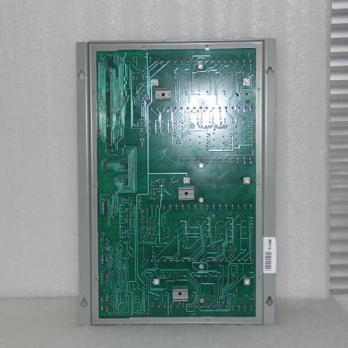
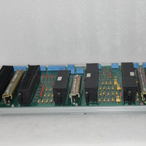
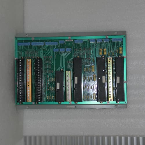
The GE DS3820TIMCRF is a specialized universal temperature input module for the Speedtronic Mark V turbine control system, providing eight isolated channels with redundant field wiring capability for critical temperature monitoring applications. This board mounts directly into the Mark V rack and interfaces with the backplane, converting temperature sensor signals into accurate digital readings while offering dual terminal connections per channel for fault-tolerant sensor wiring.
The “TIMCRF” designation indicates “Temperature, Input, Multi-Configurable, Redundant Field” — the defining feature being dual terminal blocks per channel that allow redundant wiring from the same sensor or dual sensors to be connected, with automatic switchover in case of a wiring fault. The board supports thermocouples (J, K, T), RTDs (Pt100, Ni120), and 4-20 mA transmitters, making it the most flexible and fault-tolerant temperature input module in the Mark V line. It was originally developed for GE’s most critical turbine monitoring applications—bearing temperature protection, overspeed temperature monitoring, and other safety-related measurements—where a single wiring fault cannot be allowed to cause a loss of temperature indication.
Key Technical Specifications
| Parameter | Value |
|---|---|
| Manufacturer | GE (General Electric) |
| Model Number | DS3820TIMCRF |
| Series | Speedtronic Mark V |
| Number of Channels | 8 (isolated) |
| Redundancy | Dual field wiring terminals per channel (primary and secondary) |
| Supported Input Types | Thermocouple: J, K, T; RTD: Pt100 (α=0.00385), Ni120; 4-20 mA Transmitter (loop-powered) |
| Configuration | Per-channel, software-selectable |
| Temperature Range | TC: J (-210 to +1200°C), K (-270 to +1372°C), T (-270 to +400°C); RTD: Pt100 (-200 to +850°C), Ni120 (-80 to +300°C); 4-20 mA: Scaled to engineering units |
| Resolution | 16-bit (0.1°C typical for TC/RTD; 0.001 mA for 4-20 mA) |
| Accuracy (TC) | ±0.2% of reading ±0.5°C |
| Accuracy (RTD) | ±0.1% of reading ±0.3°C |
| Accuracy (4-20 mA) | ±0.05% of span |
| Redundancy Switchover | Automatic, seamless (no data gap) |
| Input Impedance (TC) | >10 MΩ |
| RTD Excitation Current | 1 mA (selectable 0.5 mA per channel) |
| RTD Lead Compensation | Automatic (3-wire, 4-wire) |
| 4-20 mA Loop Power | 24V DC (internal, configurable per channel) |
| Cold Junction Compensation | Integrated (for thermocouple mode) |
| Open Sensor Detection | Yes (detects open circuit for both primary and secondary) |
| Common Mode Rejection | 120 dB at 50/60 Hz |
| Isolation Voltage | 2500 VDC (field-to-backplane) |
| Update Rate | 10 Hz (all channels scanned) |
| Status Indicators | 8 green LEDs (valid measurement), 1 red LED (system fault), 2 yellow LEDs per channel (primary open, secondary open) |
| Operating Temperature | 0 to +60°C (ambient, forced air required) |
| Storage Temperature | -40 to +85°C |
| Dimensions | 8.5″ x 4.2″ x 1.5″ (standard Mark V 1-slot width) |
| Connector | 96-pin DIN 41612 (Type C, male) + dual external terminal blocks (primary and secondary) |
Key Selling Points & Differentiators
- Redundant field wiring capability. Dual terminal blocks per channel allow redundant wiring from the same sensor or dual sensors, with automatic seamless switchover if one path fails. Critical for safety-related temperature monitoring.
- Three sensor types in one board. Supports thermocouples, RTDs, and 4-20 mA transmitters—eliminating the need for separate input modules.
- Independent channel configuration. Each channel independently configurable for any supported sensor type through software—no hardware jumpers required.
- Dual yellow LEDs per channel. Separate indicators for primary and secondary wiring faults, allowing rapid fault identification and targeted maintenance.
- Internal 4-20 mA loop power. No external power supply needed for loop-powered transmitters—simplifies wiring and reduces cabinet complexity.
- Automatic RTD lead compensation. For 3-wire and 4-wire RTD configurations, lead resistance is automatically compensated.
- Seamless redundancy switchover. No data gap or measurement interruption when switching from primary to secondary wiring—critical for turbine protection applications.
- 48-hour burn-in with redundancy testing. Every unit is tested with both primary and secondary paths, verifying automatic switchover and accuracy in both modes.
- 18-month warranty covering accuracy, redundancy functionality, and channel integrity. If redundancy switchover fails or channels drift beyond spec, we replace the board.
Frequently Asked Questions (FAQ)
Q: What does “RF” mean in the TIMCRF model number?
A: “RF” stands for “Redundant Field” — the board has dual terminal blocks per channel (primary and secondary) for redundant wiring from the same sensor or for dual sensors. The board automatically switches from primary to secondary if the primary circuit fails (open wire, broken connection), providing fault-tolerant temperature measurement for critical applications.
Q: How does the redundancy switchover work?
A: The board continuously monitors both primary and secondary circuits. If the primary wiring fails (open circuit), the board seamlessly switches to the secondary circuit within one scan cycle (100ms). There is no data gap or measurement interruption—the CPU sees a continuous temperature reading. A yellow LED for the failed circuit illuminates, and a diagnostic flag is sent to the CPU for alarming.
Q: Can I use the redundancy feature with all sensor types?
A: Yes—the redundancy feature works with thermocouples, RTDs, and 4-20 mA transmitters. For thermocouples and RTDs, you can wire a single sensor with redundant leads to both terminals. For 4-20 mA transmitters, you can use a transmitter with dual outputs or wire two separate transmitters to the primary and secondary terminals.
Q: What is the difference between the TIMCRF and the standard TIMC?
A: The TIMCRF adds redundancy capability—dual terminal blocks per channel and automatic switchover logic—while the TIMC has a single terminal block per channel. The TIMCRF is designed for critical temperature monitoring where a single wiring fault cannot cause loss of indication. The TIMC is for standard non-critical temperature monitoring. Accuracy and sensor support are otherwise identical.
Q: Can I use the TIMCRF without using the redundancy feature?
A: Yes—you can simply connect only the primary terminals and leave the secondary terminals unconnected. The board will operate as a standard TIMC, with no redundancy. The secondary yellow LED will indicate an open circuit (because nothing is connected), which you can ignore or mask in software.
Q: How do I wire a single RTD with redundant leads to the TIMCRF?
A: A 3-wire RTD has three leads: two excitation leads and one sense lead. For redundancy, you would wire the RTD’s two excitation leads to both the primary and secondary excitation terminals (using a split connection), and the sense lead to both the primary and secondary sense terminals. Alternatively, you can use a 4-wire RTD with separate primary and secondary leads. The user manual has detailed wiring diagrams—we can provide a copy with your board.
Q: What happens if both primary and secondary wiring fail simultaneously?
A: If both circuits fail, the board’s green LED for that channel will turn off, the yellow LEDs for both primary and secondary will illuminate, and the board will report a fault to the CPU. The temperature reading will be invalid (open circuit). This is a worst-case scenario that should be addressed immediately. The redundancy is designed to protect against single-point wiring failures, not double failures.
Q: Does the TIMCRF have conformal coating or gold-plated terminals?
A: Not in the standard version. The TIMCRF uses the standard 0°C to +60°C temperature rating with standard tin-plated terminals and no conformal coating. If you need environmental protection with redundancy, you would need a variant like DS3820TIMCRF1A1A (coated with gold-plated terminals). This variant is extremely rare—contact us for availability.
Q: What is the update rate of the TIMCRF?
A: The TIMCRF scans all 8 channels at 10 Hz (100ms per full scan) regardless of sensor type or whether redundancy is active. The redundancy switchover is seamless and does not affect the scan rate.
Q: Is the TIMCRF suitable for SIL-level safety applications?
A: The Mark V platform predates SIL certification, so the board itself does not carry a SIL rating. However, the redundancy feature makes the TIMCRF well-suited for safety-critical temperature monitoring—bearing temperatures, overspeed protection, and other applications where a single wiring fault could compromise turbine protection. The board is widely used in critical Mark V installations and is accepted by most regulatory bodies based on industry practice.
Q: What is the warranty on the TIMCRF?
A: 18 months from shipment, covering accuracy, redundancy switchover functionality, and channel integrity. If the board fails to switch over properly or channels drift beyond spec, we replace it. The warranty does not cover physical damage or miswiring.
Q: Do you have many TIMCRF boards in stock?
A: The TIMCRF is a specialized variant with limited production. We typically have 2-4 units in stock. If you need more than one or two, contact us directly to confirm availability. This board is critical for applications requiring fault-tolerant temperature monitoring—we recommend securing your requirements while stock remains.
A-B 1747-L552
FUJI V810T
ABB PPC907BE
ABB SPASI23
 Email: sales@plcfcs.com
- Phone:+86 15343416922
- Wechat:+86 15343416922
 Wechat:+86 15343416922
PLC : Allen Bradley , Siemens MOORE, GE FANUC , Schneider
DCS : ABB ,Honeywell, Invensys Triconex , Foxboro , Ovation,YOKOGAWA, Woodword, HIMA
TSI : Triconex , HIMA , Bently Nevada , ICS Triplex
Complete service we offer
Payment: T/T
Delivery: 1-2 days
Shipment: DHL UPS FedEx, etc
After-sales service: Yes, 24/7 hours