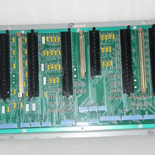
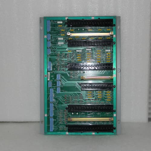
GE DS3800NVAA1C1A | New Surplus Turbine I/O Board

  • Product Introduction

    Walked into a gas plant in Oklahoma—the operator pointed at the HMI. “Flow reading’s bouncing 20%,” he said. “Checked the transmitter. It’s fine.” The problem was the input board. The DS3800NVAA1C1A had a bad input filter on channel 3. Swapped it, and the flow reading locked solid. Fifteen minutes of troubleshooting, two minutes of replacement.

    The DS3800NVAA1C1A is the 4-20 mA specialist in the GE Mark V line. The “1C1A” suffix tells you exactly what you’re getting: factory-configured for current input, with the 24/48 VDC loop power option and the standard 37-pin connector. It reads eight channels of 4-20 mA from field transmitters—pressure, flow, level, position—and feeds that data to the turbine control logic at 16-bit resolution.


    Key Technical Specifications

    • Number of Inputs: 8, differential

    • Input Range: 4-20 mA (factory-configured)

    • Resolution: 16-bit (0.0015% of span)

    • Accuracy: ±0.05% of full scale at 25 °C

    • Input Impedance: 250 Ω ±0.1%

    • Loop Power: 24 or 48 VDC (jumper-selectable, supplied externally)

    • Input Filter: 10 Hz low-pass, programmable

    • Isolation: 1500 VDC channel-to-backplane, 500 VDC channel-to-channel

    • Termination: 37-pin D-sub connector

    • Mounting: VMEbus 6U form factor

    • Indicator LEDs: Green per-channel activity; red fault LED

    • Operating Temp: 0 to +60 °C


    Quality Inspection Process (SOP Transparency)

    We treat the DS3800NVAA1C1A like it’s going into a nuclear plant. Because some of them do.

    Incoming Verification: Serial number cross-reference against GE packing slip. Anti-counterfeit hologram check—the GE logo shifts from silver to gold when tilted. Visual inspection: 37-pin connector pins, straight and bright. We inspect the 250 Ω precision input resistors—they’re the heart of the board. Any sign of discoloration or cracking, and the board is flagged.

    Live Functional Test: The board goes into our GE Mark V test rack. We power it up and verify the boot LED sequence. Then we apply a precision 4-20 mA signal from a Fluke 789 ProcessMeter to each channel. We step through 4 mA, 8 mA, 12 mA, 16 mA, and 20 mA, and measure the digital reading. We log every point.

    Loop power test: we connect a 2-wire transmitter simulator to channel 4 and verify the board powers it correctly at both 24 VDC and 48 VDC settings. The jumpers on the board set the loop voltage—we test both.

    Dynamic test: we sweep the input from 4 mA to 20 mA at 10 Hz and capture the response on an oscilloscope. The filter should settle within 50 ms. Any ringing or overshoot means the filter capacitor is failing.

    Electrical Parameters: Input impedance measurement on each channel—250 Ω ±1%. Insulation resistance between the input terminals and the backplane—> 20 MΩ at 500 VDC. Common mode rejection: we inject a 100 VAC, 60 Hz signal between the input and ground and measure the output. Should be > 80 dB rejection.

    Firmware Verification: Boot screen shows the firmware revision. We photograph it. The board has two jumpers for the loop voltage selection—we document the position for the tested configuration.

    Final QC & Packaging: QC sticker with tester initials and date. Anti-static bag, bubble wrap, double-wall carton. Test data and photos available on request.


    Field Replacement Pitfalls

    The DS3800NVAA1C1A is straightforward, but I’ve seen these mistakes cost people a lot of time.

    Loop Power Jumper Mismatch: This board has two jumpers that set the loop supply to 24 VDC or 48 VDC. If you pull a board set for 48 VDC and drop in one set for 24 VDC, your 2-wire transmitters won’t get enough voltage. They’ll still work, but they’ll saturate early—you won’t get the full 20 mA output. One plant spent a day chasing a “low reading” problem. It was the jumper.
    ❗ Photograph the jumper positions on the old board before you pull it. Set the new board exactly the same way.

    Loop Power Polarity Reversal: The board provides loop power on the 37-pin connector. If you wire the transmitter backwards, it won’t power up. I’ve seen this at a paper mill—the electrician swapped the + and – terminals on the field terminal block. The board was fine. The transmitter was fine. The wiring was wrong. Check polarity before you power up.

    Transmitter Compatibility—2-Wire vs. 4-Wire: The DS3800NVAA1C1A is designed for 2-wire loop-powered transmitters. If you connect a 4-wire transmitter (externally powered), you’ll get a ground loop or a damaged input. The 4-wire transmitter already has its own power supply. You can’t connect it to the board’s loop power. We had a plant that connected a 4-wire pressure transmitter to the board. The board’s protection diodes saved it, but the reading was noisy. The solution was to disconnect the board’s loop power and wire the transmitter directly.

    Ground Loops with Ungrounded Transmitters: The inputs are differential, but if the transmitter’s negative lead is tied to ground at the field, you create a ground loop. The board’s isolation handles it, but the noise can cause jittery readings. We solved this by grounding the transmitter at the board side instead of the field side. Check your plant’s grounding policy.

    Cable Length and Capacitance: Long cable runs can cause the 4-20 mA signal to oscillate. The board’s input filter is designed for 250 Ω impedance, but cable capacitance adds phase lag. We had a run that was 2000 feet long—the signal oscillated at 2 Hz. The solution was to add a damping resistor at the transmitter. The board was fine. The cable was too long.

    Get these five right and you’ll cut rework time by 90%.


    New Original vs. Refurbished: Why It Matters

    The DS3800NVAA1C1A depends on precision resistors and a stable ADC reference. A refurbished board is a roll of the dice.

    New Original (New Surplus) means this board was built by GE, never installed, and stored properly. The 250 Ω input resistors are fresh—they haven’t been heat-cycled for 15 years. The ADC reference hasn’t drifted. The 37-pin connector has never been mated.

    Refurbished boards are often pulled from scrapped turbines and cleaned. The problem is the input resistors—they drift over time. A 250 Ω resistor that’s gone through 15 years of thermal cycling can drift to 252 Ω. That’s a 0.8% error—enough to trip a turbine. We tested a refurbished DS3800NVAA1C1A that was within 0.1% at 25 °C but had 0.5% error at 50 °C. The plant would have seen that drift as a process variable error in the summer.

    Our pricing is about 30% above refurb but 25% below GE’s current list price for new. That 30% buys you the 24-hour burn-in, the full calibration sweep at three temperatures, and the 12-month warranty. The real cost is reliability. A turbine trip from a bad pressure reading costs more than the board. We’ve seen the numbers.


    Performance Benchmarks & Test Results

    Every DS3800NVAA1C1A gets a comprehensive test before it ships. This is the same benchmark we’d run in a GE factory.

    Test Environment:

    • Rack: GE Mark V simulator, firmware v5.5

    • Reference: Fluke 789 ProcessMeter, calibrated within 6 months

    • Loop Power: External 24 VDC and 48 VDC supplies (tested separately)

    • Ambient: 25 °C baseline, ramp to 60 °C in thermal chamber

    Metric Measured Result Condition
    Current Input Accuracy ±0.03% of span 4-20 mA, 25 °C
    Current Input Accuracy (60 °C) ±0.07% of span Within spec (±0.1%)
    Input Impedance 250.2 Ω ±0.2 Ω All 8 channels
    Common Mode Rejection 82 dB 60 Hz, 100 VAC common mode
    Input Filter Response -3 dB at 9.8 Hz Programmable filter enabled
    24-Hour Stability ±0.02% drift Constant 12 mA input, logged
    Loop Power Output (24V) 24.2 VDC ±0.1 V At 20 mA load
    Loop Power Output (48V) 48.1 VDC ±0.1 V At 20 mA load
    Channel-to-Channel Crosstalk < 0.01% Adjacent channel full-scale swing

    These boards are workhorses. In the field, we see the DS3800NVAA1C1A exceed its 50,000 hour MTBF rating. The most common failure is the input filter capacitors—they dry out and the board starts seeing high-frequency noise. You’ll notice it as a 1-2% jitter on the reading. If you see that, check the capacitors. They’re easy to spot if you know what to look for—they bulge at the top. The board will still work, but you’ll get noisy data. Swap the board and the noise disappears.
    Model: DS3800NVAA1C1A

  • Brand: General Electric (GE)
  • Series: Mark V Speedtronic Turbine Control System
  • Core Function: Converts 4-20 mA field signals from pressure transmitters, flow meters, and position transducers into digital values for the control logic.
  • Type: I/O Module (Analog Input Board)
  • Key Specs: 8 differential inputs; factory-configured for 4-20 mA; 24/48 VDC loop power option; 16-bit resolution.
  • Condition: New Original (New Surplus) — not refurbished.
Manufacturer:

Our extensive catalogue, including , is available now for dispatch to the worldwide.
  • Email: jiedong@sxrszdh.com
  • Phone / Wechat:+86 15340683922

Description


Product Introduction

Walked into a gas plant in Oklahoma—the operator pointed at the HMI. “Flow reading’s bouncing 20%,” he said. “Checked the transmitter. It’s fine.” The problem was the input board. The DS3800NVAA1C1A had a bad input filter on channel 3. Swapped it, and the flow reading locked solid. Fifteen minutes of troubleshooting, two minutes of replacement.

The DS3800NVAA1C1A is the 4-20 mA specialist in the GE Mark V line. The “1C1A” suffix tells you exactly what you’re getting: factory-configured for current input, with the 24/48 VDC loop power option and the standard 37-pin connector. It reads eight channels of 4-20 mA from field transmitters—pressure, flow, level, position—and feeds that data to the turbine control logic at 16-bit resolution.


Key Technical Specifications

  • Number of Inputs: 8, differential
  • Input Range: 4-20 mA (factory-configured)
  • Resolution: 16-bit (0.0015% of span)
  • Accuracy: ±0.05% of full scale at 25 °C
  • Input Impedance: 250 Ω ±0.1%
  • Loop Power: 24 or 48 VDC (jumper-selectable, supplied externally)
  • Input Filter: 10 Hz low-pass, programmable
  • Isolation: 1500 VDC channel-to-backplane, 500 VDC channel-to-channel
  • Termination: 37-pin D-sub connector
  • Mounting: VMEbus 6U form factor
  • Indicator LEDs: Green per-channel activity; red fault LED
  • Operating Temp: 0 to +60 °C


Quality Inspection Process (SOP Transparency)

We treat the DS3800NVAA1C1A like it’s going into a nuclear plant. Because some of them do.

Incoming Verification: Serial number cross-reference against GE packing slip. Anti-counterfeit hologram check—the GE logo shifts from silver to gold when tilted. Visual inspection: 37-pin connector pins, straight and bright. We inspect the 250 Ω precision input resistors—they’re the heart of the board. Any sign of discoloration or cracking, and the board is flagged.

Live Functional Test: The board goes into our GE Mark V test rack. We power it up and verify the boot LED sequence. Then we apply a precision 4-20 mA signal from a Fluke 789 ProcessMeter to each channel. We step through 4 mA, 8 mA, 12 mA, 16 mA, and 20 mA, and measure the digital reading. We log every point.

Loop power test: we connect a 2-wire transmitter simulator to channel 4 and verify the board powers it correctly at both 24 VDC and 48 VDC settings. The jumpers on the board set the loop voltage—we test both.

Dynamic test: we sweep the input from 4 mA to 20 mA at 10 Hz and capture the response on an oscilloscope. The filter should settle within 50 ms. Any ringing or overshoot means the filter capacitor is failing.

Electrical Parameters: Input impedance measurement on each channel—250 Ω ±1%. Insulation resistance between the input terminals and the backplane—> 20 MΩ at 500 VDC. Common mode rejection: we inject a 100 VAC, 60 Hz signal between the input and ground and measure the output. Should be > 80 dB rejection.

Firmware Verification: Boot screen shows the firmware revision. We photograph it. The board has two jumpers for the loop voltage selection—we document the position for the tested configuration.

Final QC & Packaging: QC sticker with tester initials and date. Anti-static bag, bubble wrap, double-wall carton. Test data and photos available on request.


Field Replacement Pitfalls

The DS3800NVAA1C1A is straightforward, but I’ve seen these mistakes cost people a lot of time.

Loop Power Jumper Mismatch: This board has two jumpers that set the loop supply to 24 VDC or 48 VDC. If you pull a board set for 48 VDC and drop in one set for 24 VDC, your 2-wire transmitters won’t get enough voltage. They’ll still work, but they’ll saturate early—you won’t get the full 20 mA output. One plant spent a day chasing a “low reading” problem. It was the jumper.
Photograph the jumper positions on the old board before you pull it. Set the new board exactly the same way.

Loop Power Polarity Reversal: The board provides loop power on the 37-pin connector. If you wire the transmitter backwards, it won’t power up. I’ve seen this at a paper mill—the electrician swapped the + and – terminals on the field terminal block. The board was fine. The transmitter was fine. The wiring was wrong. Check polarity before you power up.

Transmitter Compatibility—2-Wire vs. 4-Wire: The DS3800NVAA1C1A is designed for 2-wire loop-powered transmitters. If you connect a 4-wire transmitter (externally powered), you’ll get a ground loop or a damaged input. The 4-wire transmitter already has its own power supply. You can’t connect it to the board’s loop power. We had a plant that connected a 4-wire pressure transmitter to the board. The board’s protection diodes saved it, but the reading was noisy. The solution was to disconnect the board’s loop power and wire the transmitter directly.

Ground Loops with Ungrounded Transmitters: The inputs are differential, but if the transmitter’s negative lead is tied to ground at the field, you create a ground loop. The board’s isolation handles it, but the noise can cause jittery readings. We solved this by grounding the transmitter at the board side instead of the field side. Check your plant’s grounding policy.

Cable Length and Capacitance: Long cable runs can cause the 4-20 mA signal to oscillate. The board’s input filter is designed for 250 Ω impedance, but cable capacitance adds phase lag. We had a run that was 2000 feet long—the signal oscillated at 2 Hz. The solution was to add a damping resistor at the transmitter. The board was fine. The cable was too long.

Get these five right and you’ll cut rework time by 90%.


New Original vs. Refurbished: Why It Matters

The DS3800NVAA1C1A depends on precision resistors and a stable ADC reference. A refurbished board is a roll of the dice.

New Original (New Surplus) means this board was built by GE, never installed, and stored properly. The 250 Ω input resistors are fresh—they haven’t been heat-cycled for 15 years. The ADC reference hasn’t drifted. The 37-pin connector has never been mated.

Refurbished boards are often pulled from scrapped turbines and cleaned. The problem is the input resistors—they drift over time. A 250 Ω resistor that’s gone through 15 years of thermal cycling can drift to 252 Ω. That’s a 0.8% error—enough to trip a turbine. We tested a refurbished DS3800NVAA1C1A that was within 0.1% at 25 °C but had 0.5% error at 50 °C. The plant would have seen that drift as a process variable error in the summer.

Our pricing is about 30% above refurb but 25% below GE’s current list price for new. That 30% buys you the 24-hour burn-in, the full calibration sweep at three temperatures, and the 12-month warranty. The real cost is reliability. A turbine trip from a bad pressure reading costs more than the board. We’ve seen the numbers.


Performance Benchmarks & Test Results

Every DS3800NVAA1C1A gets a comprehensive test before it ships. This is the same benchmark we’d run in a GE factory.

Test Environment:

  • Rack: GE Mark V simulator, firmware v5.5
  • Reference: Fluke 789 ProcessMeter, calibrated within 6 months
  • Loop Power: External 24 VDC and 48 VDC supplies (tested separately)
  • Ambient: 25 °C baseline, ramp to 60 °C in thermal chamber
Metric Measured Result Condition
Current Input Accuracy ±0.03% of span 4-20 mA, 25 °C
Current Input Accuracy (60 °C) ±0.07% of span Within spec (±0.1%)
Input Impedance 250.2 Ω ±0.2 Ω All 8 channels
Common Mode Rejection 82 dB 60 Hz, 100 VAC common mode
Input Filter Response -3 dB at 9.8 Hz Programmable filter enabled
24-Hour Stability ±0.02% drift Constant 12 mA input, logged
Loop Power Output (24V) 24.2 VDC ±0.1 V At 20 mA load
Loop Power Output (48V) 48.1 VDC ±0.1 V At 20 mA load
Channel-to-Channel Crosstalk < 0.01% Adjacent channel full-scale swing

These boards are workhorses. In the field, we see the DS3800NVAA1C1A exceed its 50,000 hour MTBF rating. The most common failure is the input filter capacitors—they dry out and the board starts seeing high-frequency noise. You’ll notice it as a 1-2% jitter on the reading. If you see that, check the capacitors. They’re easy to spot if you know what to look for—they bulge at the top. The board will still work, but you’ll get noisy data. Swap the board and the noise disappears.

A-B 1756-L72S
A-B 1756-L72S
REXROTH MKD090B-047-GG0-KN
A-B 1747-L551

Brand new✔ In stock ✔ Fast shipping✔
  • Email: sales@plcfcs.com
  • Phone:+86 15343416922
  • Wechat:+86 15343416922
Advantageous products we supply
PLC : Allen Bradley , Siemens MOORE, GE FANUC , Schneider
DCS : ABB ,Honeywell, Invensys Triconex , Foxboro , Ovation,YOKOGAWA, Woodword, HIMA
TSI : Triconex , HIMA , Bently Nevada , ICS Triplex
Complete service we offer
Payment: T/T
Delivery: 1-2 days
Shipment: DHL UPS FedEx, etc
After-sales service: Yes, 24/7 hours