 Email: jiedong@sxrszdh.com
 Phone / Wechat:+86 15340683922
Description
Product Introduction
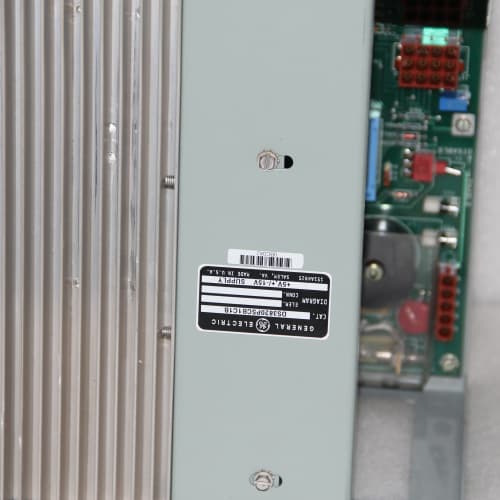
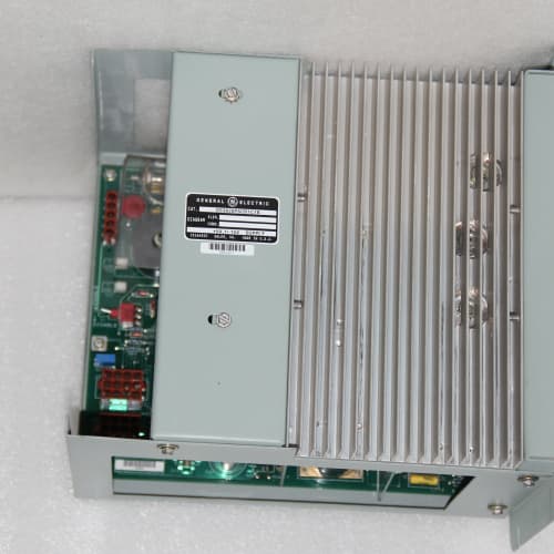
I walked into a paper mill in Oregon, and the control room had a board sitting on the bench. The maintenance guy said, “It passed the test rack, but the valve keeps hunting.” That board was a DS3800NUVA1C1B. They’d swapped it, but the hunting continued. Turned out they’d pulled the wrong variant—the “C” suffix expects a 24/48 VDC field supply, and they’d wired it for 125 VDC. We dropped in the right variant and the valve smoothed out in seconds.
The DS3800NUVA1C1B is the low-voltage sibling in the GE Mark V analog output family. The “1C1B” suffix tells you the board is factory-configured for 4-20 mA current output with a 24/48 VDC field supply option. It drives actuators, positioners, and I/P converters—anywhere you need a controlled 4-20 mA signal but don’t have 125 VDC in the loop.
Key Technical Specifications
- Number of Outputs: 8, fully isolated
- Output Range: 4-20 mA (factory-configured)
- Resolution: 12-bit (4096 steps)
- Accuracy: ±0.1% of full scale at 25 °C
- Load Impedance: 0-600 Ω
- Field Supply: 24 or 48 VDC (jumper-selectable)
- Update Rate: 1 ms per channel (8 ms full scan)
- Isolation: 1500 VDC channel-to-backplane, 500 VDC channel-to-channel
- Termination: 37-pin D-sub connector
- Mounting: VMEbus 6U form factor
- Indicator LEDs: Green output active per channel; red fault LED
- Operating Temp: 0 to +60 °C
Quality Inspection Process (SOP Transparency)
Every DS3800NUVA1C1B that comes through our shop gets the full treatment. We don’t shortcut this one.
Incoming Verification: Serial number matching GE packing slip. Anti-counterfeit hologram check—the GE logo shifts from blue to gold when you tilt it. Visual inspection: 37-pin connector pins are straight, no oxidation on the gold plating. We check the jumper headers on the board—there are two jumpers that select the field supply voltage (24 or 48 VDC). We confirm they’re set correctly. If they’re bent or missing, we replace them.
Live Functional Test: The board goes into our GE Mark V test rack. We fire it up and watch the boot sequence. Then we run the full channel sweep: 4 mA, 8 mA, 12 mA, 16 mA, 20 mA, and back down. We measure each point with a Fluke 789 ProcessMeter through a 250 Ω precision load. We also test the 48 VDC setting by flipping the jumpers and re-running the sweep.
Dynamic test: we toggle each channel from 4 mA to 20 mA at 1 kHz and capture the settling time on an oscilloscope. This catches sluggish output drivers. We also run a “noise floor” test—measure the output with the DAC set to mid-range and look for any AC ripple on the signal.
Electrical Parameters: Insulation resistance between the output terminals and the backplane—minimum 20 MΩ at 500 VDC. We also check the output impedance by measuring the voltage drop under load. It should be less than 0.1 V at 20 mA.
Firmware Verification: We read the firmware revision from the boot screen and photograph it. The DS3800NUVA1C1B has no customer-accessible jumpers beyond the voltage selection, so that’s documented. We log all test data to a report that goes with the board.
Final QC & Packaging: QC sticker with the tester’s initials and the test date. The board goes into a fresh anti-static bag, then bubble wrap, then a double-wall carton with edge protectors. Test photos and video are available on request—we keep a record of every unit.
Field Replacement Pitfalls
The DS3800NUVA1C1B is the low-voltage version, and that creates its own set of traps. Here’s what I’ve seen.
Voltage Jumper Configuration: This board has two jumpers that select 24 VDC or 48 VDC field supply. If you pull the old board and don’t note the jumper positions, you might drop in a board set for 48 VDC into a 24 VDC field system. The board will power up, but the output current will be limited—you won’t get the full 20 mA. One plant spent three days troubleshooting a valve that wouldn’t open fully. It was the jumper.
❗ Photograph the jumper positions on the old board before you pull it. Set the new board exactly the same way.
Field Supply Voltage Drop: The board expects a clean supply at the 37-pin connector. If the field wiring is undersized or the supply is shared with other loads, voltage drop can cause the outputs to go nonlinear. We’ve measured boards where the supply dropped to 19 VDC during a 20 mA output. The board couldn’t drive the actuator to full stroke. Check the voltage at the board’s connector with all channels at 20 mA.
Loop Power vs. Passive Output: The DS3800NUVA1C1B is a passive sinking output—it doesn’t source loop power. It needs an external supply in the loop. Some actuators have built-in loop power, some don’t. If you connect a board to an actuator that expects a self-powered source, you’ll get no signal. I’ve seen this mistake cost a day of troubleshooting. Check your actuator’s loop power requirement.
Ground Loops with 24 VDC Systems: The 24 VDC field supply is often referenced to chassis ground in the actuator. If the board’s output common is also tied to ground through the backplane, you can create a ground loop. The loop current splits between the actuator and the ground path, causing inaccuracy. We solved this by isolating the actuator power supply from ground. The board’s isolation handles it, but the field wiring needs to match.
D-sub Connector Pin Wear: The 37-pin connector on this board is often cycled multiple times during maintenance. The pins are gold-plated, but they wear. If the replacement board’s connector has insertion wear from previous use, you can get intermittent connections. A new board has bright gold pins—no wear. This is one reason we push for new surplus over refurbished.
Get these five right and you’ll cut rework time by 90%.
New Original vs. Refurbished: Why It Matters
The low-voltage DS3800NUVA1C1B has a unique risk profile. The 24/48 VDC field supply means the output drivers operate at lower voltage but higher current. That means more heat in the output transistors.
New Original (New Surplus) means the board was made by GE, never installed, and stored properly. The output drivers are fresh. The DAC reference hasn’t drifted. The 37-pin connector has never been mated. The board hasn’t been sitting in a hot turbine cabinet for 10 years, baking the capacitors.
Refurbished boards are often pulled from decommissioned turbines, cleaned, and resold. The problem is the output driver transistors—they degrade with thermal cycling. A refurb board might pass a bench test but fail in the field when the cabinet hits 50 °C. We tested a refurbished DS3800NUVA1C1B that was within 0.1% at 25 °C but had 1.5% error at 50 °C. That’s a valve that drifts out of position on a summer afternoon. The plant had a turbine trip at 2 PM on a 40 °C day.
We price this board about 30% above refurb but 25% below GE’s current list price. That premium buys the 24-hour burn-in, the full calibration sweep at temperature, and the 12-month warranty. And it buys peace of mind. One unscheduled shutdown on a 50 MW turbine costs more than the board—a lot more. We’ve seen the repair bills.
Performance Benchmarks & Test Results
We run a standardized benchmark on every DS3800NUVA1C1B before it ships. This is the same test we’d run in a GE factory.
Test Environment:
- Rack: GE Mark V simulator, firmware v5.5
- Load: 250 Ω precision resistor (0.01% tolerance)
- Reference: Fluke 789 ProcessMeter, calibrated within 6 months
- Supply: External 24 VDC and 48 VDC (tested separately)
- Ambient: 25 °C baseline, ramp to 60 °C in thermal chamber
| Metric | Measured Result | Condition |
|---|---|---|
| Current Output Accuracy (24V) | ±0.04% of span | 4-20 mA, 25 °C |
| Current Output Accuracy (48V) | ±0.04% of span | 4-20 mA, 25 °C |
| Current Output Accuracy (60 °C) | ±0.08% of span | With 48 VDC supply |
| DAC Monotonicity | 100% verified | No missing codes |
| Settling Time | 1.3 ms | 4 to 20 mA step |
| Output Noise (RMS) | 0.5 mV | 10 Hz to 100 kHz |
| Load Regulation | ±0.01% of span | 0 to 600 Ω load |
| Supply Rejection | < 0.02% / V | 24 VDC ±10% variation |
| 24-Hour Stability | ±0.03% drift | Constant 12 mA, logged |
In field use, these boards are reliable. The low-voltage version tends to run cooler than the 125 VDC version, which extends component life. We see them exceed the 50,000 hour MTBF rating in most applications. The one place they struggle is with long cable runs—if you’re driving an actuator 500 feet away, the cable capacitance can cause ringing on the output. We measured a 5% overshoot on a 1000-foot cable. If your runs are long, you might need a loop-powered isolator or a dedicated output driver. The board itself is solid.
ABB IPS21-35AD
ABB CI858
BENTLY 3500/22-01-01-01
 Email: sales@plcfcs.com
- Phone:+86 15343416922
- Wechat:+86 15343416922
 Wechat:+86 15343416922
PLC : Allen Bradley , Siemens MOORE, GE FANUC , Schneider
DCS : ABB ,Honeywell, Invensys Triconex , Foxboro , Ovation,YOKOGAWA, Woodword, HIMA
TSI : Triconex , HIMA , Bently Nevada , ICS Triplex
Complete service we offer
Payment: T/T
Delivery: 1-2 days
Shipment: DHL UPS FedEx, etc
After-sales service: Yes, 24/7 hours