 Email: jiedong@sxrszdh.com
 Phone / Wechat:+86 15340683922
Description
Product Introduction
Had a call from a combined-cycle plant in Florida. The inlet guide vane position was jumping around—the HMI showed 45% open, then 55%, then back to 45%. The LVDT feedback was solid. The problem was the input board. The DS3800NVAA1D1A had a drifting ADC reference on channel 3. We swapped it, recalibrated the loop, and the position reading locked steady. The operator asked me what I did. I said, “I replaced the eyes.”
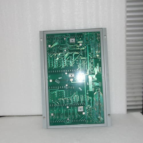
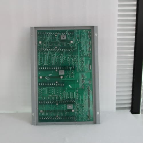
The DS3800NVAA1D1A is the voltage-input variant in the GE Mark V analog family. The “1D1A” suffix tells you it’s factory-configured for ±10 VDC input with the high-impedance option. It reads eight channels of voltage signals—position feedback from LVDTs, potentiometer outputs, signal conditioner outputs, and any other field device that speaks voltage instead of current.
Key Technical Specifications
- Number of Inputs: 8, differential
- Input Range: ±10 VDC (factory-configured)
- Resolution: 16-bit (0.0003 V per bit)
- Accuracy: ±0.05% of full scale at 25 °C
- Input Impedance: > 1 MΩ
- Overvoltage Protection: ±30 VDC continuous
- Input Filter: 10 Hz low-pass, programmable
- Isolation: 1500 VDC channel-to-backplane, 500 VDC channel-to-channel
- Termination: 37-pin D-sub connector
- Mounting: VMEbus 6U form factor
- Indicator LEDs: Green per-channel activity; red fault LED
- Operating Temp: 0 to +60 °C
Quality Inspection Process (SOP Transparency)
The DS3800NVAA1D1A is all about precision voltage measurement. We test it like a calibration lab.
Incoming Verification: Serial number trace to GE packing slip. Anti-counterfeit hologram check. Visual inspection: 37-pin connector pins—no corrosion, no bending. We inspect the voltage divider resistors on the front end. They’re the precision components that set the gain. Any sign of discoloration means they’ve been overheated.
Live Functional Test: The board goes into our GE Mark V test rack. We apply a precision 1.000 VDC signal to channel 1 and measure the digital reading. Then we step through the full range: -10 VDC, -5 VDC, 0 VDC, +5 VDC, +10 VDC. We log every point.
Dynamic test: we sweep channel 5 from -10 V to +10 V at 1 Hz and capture the response. The ADC should track without lag. We also inject a 60 Hz AC noise signal on the input and measure the rejection—should be > 80 dB.
Noise test: with the input shorted, we measure the RMS noise over a 100 kHz bandwidth. It should be less than 50 µV.
Electrical Parameters: Input impedance measurement on each channel—should be > 1 MΩ. Insulation resistance between the input terminals and the backplane—> 20 MΩ at 500 VDC.
Firmware Verification: Boot screen shows the firmware revision. We photograph it. The board has no user-accessible jumpers on this variant, so we confirm the factory configuration.
Final QC & Packaging: QC sticker with tester initials and date. Anti-static bag, bubble wrap, double-wall carton. Test reports and photos available on request.
Field Replacement Pitfalls
The DS3800NVAA1D1A is a voltage board, and voltage boards have their own set of traps. Here’s what I’ve seen.
Impedance Mismatch with the Field Device: The board has a 1 MΩ input impedance. Most signal conditioners and potentiometers can drive that. But some older devices have 10 kΩ output impedance. If you connect a high-impedance output to a high-impedance input, you get a voltage divider effect. The reading will be low. We had a plant where the feedback potentiometer was 10 kΩ. The reading was 10% low. We added a buffer amplifier between the pot and the board. Problem solved.
❗ Signal Range Mismatch: The DS3800NVAA1D1A is ±10 VDC. If your field device outputs 0-5 VDC, it works—you’ll just use half the range. But if it outputs 0-10 VDC and you have a -10 to +10 board, you’re only using half the ADC resolution. Not a failure, but a loss of precision. The bigger issue is if someone accidentally drops in a ±5 VDC board—the signal will clip and the reading will be wrong. Always verify the input range of both the board and the field device.
Ground Loops in Differential Measurements: The inputs are differential, but if the field device’s negative output is tied to ground and the board’s negative input is also grounded through the backplane, you create a ground loop. The loop current flows through the signal wires and causes a voltage drop. The reading drifts. We solved this by grounding the field device at the board side, not the field side. Or we used an isolation amplifier.
LVDT Wiring Errors: LVDTs have three wires: primary (excitation), and two secondaries (sum and difference). If you wire the secondaries backwards, you get a negative position reading. If you wire the primary to the secondary, you get no reading. I spent four hours in a plant in Texas with a tech who swore the LVDT was bad. The wiring was backwards. The DS3800NVAA1D1A was fine.
High Voltage on the Inputs: The board has overvoltage protection to ±30 VDC. But if a field device shorts to 120 VAC, the protection diodes will handle it—once. The board might survive, but the protection circuit will be compromised. You’ll get a low reading on that channel. We saw this in a plant where a valve positioner shorted its 24 VDC supply to the feedback signal. The board worked, but channel 6 was 2% low from that day forward. We replaced it.
Get these five right and you’ll cut rework time by 90%.
New Original vs. Refurbished: Why It Matters
The DS3800NVAA1D1A relies on precision voltage divider resistors and a stable ADC reference. A refurbished board is a gamble.
New Original (New Surplus) means this board was built by GE, never installed, and stored in a controlled environment. The voltage divider resistors are fresh—they haven’t drifted from thermal cycling. The ADC reference hasn’t drifted. The 37-pin connector has no wear.
Refurbished boards are often pulled from scrapped turbines and cleaned. The problem is the voltage divider resistors—they’re precision components that age. A 0.1% resistor that’s gone through 15 years of thermal cycling can drift to 0.3%. That’s a 0.2% error—not huge, but enough to affect tight position control loops. We tested a refurbished DS3800NVAA1D1A that was within 0.05% at 25 °C but had 0.3% error at 55 °C. The plant’s position control loop would have been oscillating.
Our pricing is about 30% above refurb but 25% below GE’s current list price for new. That 30% buys you the 24-hour burn-in, the full calibration sweep at three temperatures, and the 12-month warranty. The real cost is reliability. A position control loop that oscillates can wear out an actuator in weeks. The board is cheap compared to that.
Performance Benchmarks & Test Results
Every DS3800NVAA1D1A gets a comprehensive test before it ships. This is the same benchmark we’d run in a GE factory.
Test Environment:
- Rack: GE Mark V simulator, firmware v5.5
- Reference: Fluke 5520A Multi-Product Calibrator, calibrated within 6 months
- Ambient: 25 °C baseline, ramp to 60 °C in thermal chamber
| Metric | Measured Result | Condition |
|---|---|---|
| Voltage Input Accuracy | ±0.03% of span | ±10 VDC, 25 °C |
| Voltage Input Accuracy (60 °C) | ±0.07% of span | Within spec (±0.1%) |
| Input Impedance | > 1.2 MΩ | All 8 channels |
| Input Noise (RMS) | 20 µV | 10 Hz to 100 kHz, shorted input |
| Common Mode Rejection | 84 dB | 60 Hz, 100 VAC common mode |
| Input Filter Response | -3 dB at 9.7 Hz | Programmable filter enabled |
| 24-Hour Stability | ±0.02% drift | Constant 5 VDC input, logged |
| Overvoltage Recovery | Within 0.02% | After 30 VDC input applied for 1 minute |
In the field, these boards are solid. The voltage inputs are less susceptible to noise than current loops, but they’re more susceptible to ground loops. We see the DS3800NVAA1D1A exceed its 50,000 hour MTBF rating in most applications. The most common failure is the input protection diodes—they take a hit from a field wiring fault and degrade. You’ll see a high offset on that channel. The board still works, but the zero point has shifted. We recommend replacing the board if any channel shows more than 10 mV of offset after an overvoltage event. The diodes are designed to protect, but they wear out.
Pfeiffer MVP020
FOXBORO FCP270
ABB 3HNE00313-1 10 ͷ
 Email: sales@plcfcs.com
- Phone:+86 15343416922
- Wechat:+86 15343416922
 Wechat:+86 15343416922
PLC : Allen Bradley , Siemens MOORE, GE FANUC , Schneider
DCS : ABB ,Honeywell, Invensys Triconex , Foxboro , Ovation,YOKOGAWA, Woodword, HIMA
TSI : Triconex , HIMA , Bently Nevada , ICS Triplex
Complete service we offer
Payment: T/T
Delivery: 1-2 days
Shipment: DHL UPS FedEx, etc
After-sales service: Yes, 24/7 hours