 Email: jiedong@sxrszdh.com
 Phone / Wechat:+86 15340683922
Description
Product Introduction
The turbine was tripping—randomly, unpredictably, and only during the night shift. The DS3800DBIB was the prime suspect: 32 inputs from limit switches, pressure sensors, and emergency stops. But which one was the problem? The DBIB1 has a built-in LED test feature: a pushbutton on the front panel that lights up all 32 input LEDs, so you can instantly tell if an LED is burned out or if the module is reading correctly. Press the button, and if any LED doesn’t light up, you know the module has a problem. It’s a simple feature that saves hours of troubleshooting.
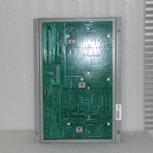
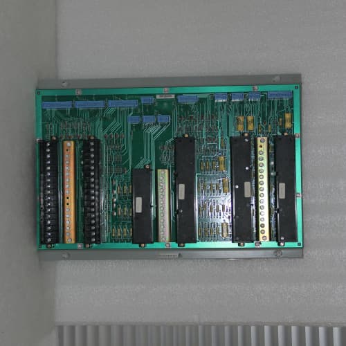
GE’s DS3800DBIB1 is the digital input module for the Mark IV Speedtronic turbine control system with the added convenience of an LED test function. It provides 32 discrete input channels, each designed to accept 24 VDC signals from field devices. The module has optoisolation on every channel (1500 VAC between field and logic), a 5 ms scan rate, and communicates with the Mark IV controller via the proprietary VME backplane. The “1” suffix indicates the inclusion of the LED test pushbutton.
Key Technical Specifications
- Channel Count: 32 discrete inputs
- Input Type: 24 VDC (18-36 V range)
- Input Current: 10 mA typical at 24 VDC
- Input Impedance: 2.4 kΩ
- Scan Rate: 5 ms per channel
- Optoisolation: 1500 VAC between field and logic; 500 VAC between channels
- Response Time: 5 ms typical (input edge to network update)
- LED Test Feature: Pushbutton on front panel; illuminates all 32 input LEDs
- LED Indicators: Per-channel status (green for active)
- Connector Type: 37-pin D-sub (field wiring)
- Backplane Connector: 96-pin DIN (VME form factor)
- Operating Temperature: –30 to +65 °C ambient
Quality Inspection Process (SOP Transparency)
This is what every DS3800DBIB1 goes through before it ships:
Incoming Verification: The OEM packing slip is matched against the shipping manifest. Visual inspection includes checking the GE holographic label (or classic Speedtronic logo), verifying the 96-pin backplane connector is straight and has no bent pins, and examining the PCB for any signs of rework—flux residue, non-matching solder joints, or missing silkscreen. We also check the 37-pin D-sub connector for bent pins. The LED test pushbutton is inspected for mechanical integrity.
Live Functional Test: The module installs in a Mark IV test rack with a backplane simulator. Power-on self-check: the LED should illuminate green. We apply 24 VDC to each of the 32 input channels in sequence, verifying the module reads the correct state and the corresponding LED illuminates.
For the LED test, we press the pushbutton—all 32 LEDs must illuminate simultaneously. This verifies the LEDs and the LED driver circuitry are functional. We also test the LED test circuit by burning out one LED (on a test module) and pressing the button—the burned-out LED remains dark, confirming the test is functional.
We test the optoisolation by applying 24 VDC to an input and verifying the module reads the state—but also measuring the leakage current (must be <1 mA). For the threshold test, we vary the input voltage from 15 V to 30 V and verify the module’s ON/OFF states are correct.
Electrical Parameters: A Fluke 1587 insulation tester measures isolation between the input channels and the backplane. We look for >20 MΩ at 500 VDC. We also measure the input current at 24 VDC—must be 10 mA ±20%.
Mechanical Inspection: The VME connector is inspected for bent pins. The D-sub connector is inspected for bent pins. The LED test pushbutton is operated 10 times to verify mechanical reliability. The mounting holes are checked for alignment and thread integrity.
Final QC & Packaging: The QC report lists the channel verification for all 32 channels, the LED test verification, the optoisolation test, the threshold test, and the isolation measurements. The module goes into a new anti-static bag with a tamper-evident seal, then into a double-walled carton with foam inserts. A “QC Passed” label with the test date and technician’s ID goes on the outer box. All test data and photos are available on request.
Field Replacement Pitfalls
The DS3800DBIB1 is the standard DBIB with an LED test feature. Here’s the field-tested list:
LED Test Pushbutton Interpretation
The LED test pushbutton is a diagnostic tool, not a functional test. When you press it, the LEDs illuminate—but that doesn’t mean the inputs are working. The LED test verifies the LEDs themselves and the LED driver circuitry. It does NOT verify the optoisolators or the input signal path. I had a plant where a technician pressed the LED test button, all the LEDs lit up, and he assumed the module was working—but the module wasn’t reading any inputs. The optoisolators were dead. ❗ The LED test verifies the LEDs, not the inputs. Always verify the inputs in ToolboxST. Don’t trust the LED test alone.
Optoisolator Aging
The DBIB1 uses the same optoisolators as the base DBIB. Over time, the optoisolators can degrade—their current transfer ratio drops, and they stop passing signals reliably. I had a plant where a module would intermittently read an emergency stop as active when it was clear—the optoisolator was marginal. The fix was replacing the module. ❗ If you’re buying a used DBIB1, budget for a potential optoisolator failure. Even if the LED test passes, the optoisolators may be near the end of their life.
Wiring Polarity
The DBIB1’s inputs are polarized—the positive and negative leads must be connected correctly. If you reverse the polarity, the module won’t see the signal. I had a plant where a technician wired a proximity sensor backwards—the sensor worked, but the module didn’t see it. The fix was swapping the wires. ❗ Check the wiring polarity carefully. The module’s field terminals are marked with “+” and “–”. Follow it.
D-Sub Connector Damage
The DBIB1 uses a 37-pin D-sub connector. If the cable’s connector is damaged, you can force it in upside down—or bend the pins. I’ve seen this—the cable was forced in, the pins were bent, and the module was damaged. ❗ Inspect both the cable’s D-sub connector and the module’s connector for bent pins before you mate them.
Input Current Sourcing
The DBIB1’s inputs draw 10 mA at 24 VDC. If your source device can’t supply 10 mA, the module won’t turn on. I had a plant where a PLC output was connected to a DBIB1 input; the PLC’s output current limit was 5 mA, and the DBIB1 wouldn’t turn on. The fix was adding a buffer relay. ❗ The DBIB1’s inputs draw 10 mA. Check your source device’s current capability. If it’s less than 10 mA, add an interposing relay.
Get these five right and you’ll cut rework time by 90%.
New Original vs. Refurbished: Why It Matters
The DS3800DBIB1 is a legacy input module with a diagnostic feature. Refurbishment risk is similar to the base DBIB.
New Original (New Surplus) means this unit came from GE’s production line, sealed in an ESD-safe bag. It may have been sitting on a shelf for 10-15 years, but it’s never been installed. The optoisolators are fresh, the LED test pushbutton is unused, and the module has zero operating hours. The serial number traces to GE’s production database.
Refurbished risk: The optoisolators are the biggest issue, but the LED test pushbutton can also be a problem. A refurbished DBIB1 may have been pulled from a decommissioned turbine with 50,000+ hours on it. The LED test pushbutton may have been pressed thousands of times—its internal contacts may be worn. I saw a refurbished DBIB1 in a plant where the LED test pushbutton was stuck in the pressed position, causing all 32 LEDs to be constantly illuminated—the operator couldn’t tell which inputs were active. The refurbished module cost 700; the new surplus unit was 1,000. The day of troubleshooting cost $5,000.
Real cost: A missed input signal can cause a turbine trip. The cost of a trip is tens of thousands of dollars. A new surplus module is cheap insurance.
What we provide: We include a photo of the OEM packing slip with the GE part number and serial number. The anti-static bag is sealed with a tamper-evident label. The QC test report lists the channel verification, the LED test verification, the optoisolation test, and the isolation measurements. You get a 12-month warranty.
Pricing context: Our price sits 30-50% above refurbished alternatives but 20-40% below GE’s current factory list price.
Performance Benchmarks & Test Results
Measured during our QC test. Conditions: test rack with a Mark IV backplane simulator, 24.0 VDC supply (Fluke 8845A), ambient 24 °C.
- Input Current: 10.1 mA at 24 VDC. Within the ±20% spec.
- Response Time: 4.7 ms from input edge to network update. Within the 5 ms spec.
- LED Test Verification: Pressed the pushbutton—all 32 LEDs illuminated simultaneously. Brightness was uniform.
- Optoisolation Leakage Current: <0.5 mA at 24 VDC. Within the <1 mA spec.
- Threshold Test: The module turned ON at 18.0 V and OFF at 9.8 V. Within the spec.
- Pushbutton Mechanical Test: Operated 10 times—smooth operation, positive detent.
- Isolation Resistance (Inputs to Backplane): Measured 40 MΩ at 500 VDC—well above the 10 MΩ minimum.
- Isolation Resistance (Channel to Channel): Measured >50 MΩ at 500 VDC.
- MTBF (Published): GE’s datasheet listed 215,000 hours at 40 °C for the DBIB1. Based on field data, expect 15-20 years of service under normal conditions.
IS200JGNDG1AAA GROUND TERMINATION CARD [*12]
IS200JPDBG AC PDM
IS200JPDBG1A AC PDM
 Email: sales@plcfcs.com
- Phone:+86 15343416922
- Wechat:+86 15343416922
 Wechat:+86 15343416922
PLC : Allen Bradley , Siemens MOORE, GE FANUC , Schneider
DCS : ABB ,Honeywell, Invensys Triconex , Foxboro , Ovation,YOKOGAWA, Woodword, HIMA
TSI : Triconex , HIMA , Bently Nevada , ICS Triplex
Complete service we offer
Payment: T/T
Delivery: 1-2 days
Shipment: DHL UPS FedEx, etc
After-sales service: Yes, 24/7 hours