 Email: jiedong@sxrszdh.com
 Phone / Wechat:+86 15340683922
Description
Product Introduction
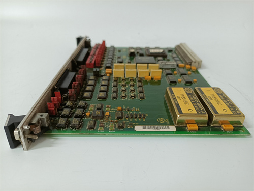
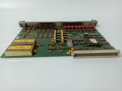
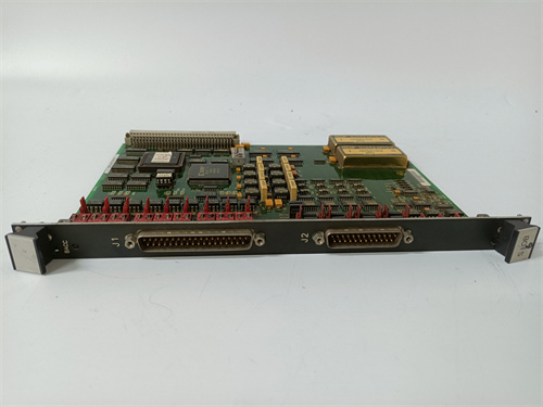
The GE DS200VPBLG1ACC functions as the Vibration Protection Board (VPBL) within the Mark VIe control platform, providing continuous monitoring of turbine shaft vibration, bearing wear, and rotating machinery health. This module accepts up to four vibration sensor inputs (proximity probes or accelerometers), processes the signals through configurable filters and alarms, and reports vibration amplitude, phase, and frequency data to the Mark VIe controller via ISBus communication.
The primary differentiator is the integrated protection logic that can trigger turbine trips or control actions when vibration levels exceed user-defined thresholds—without relying on the main controller. This reduces trip response time to approximately 20 ms, compared to 100-150 ms when using the controller alone. The ACC revision includes enhanced diagnostic reporting (sensor health, cable open-circuit detection, and vibration trend analysis), configurable on a per-channel basis for standard Mark VIe configurations.
Key Technical Specifications
| Parameter | Value |
|---|---|
| Model Number | DS200VPBLG1ACC |
| Manufacturer | GE Energy (now GE Vernova) |
| Series | Mark VIe |
| Function | Vibration Protection Board – Continuous Monitoring and Protection for Turbine Shaft and Bearings |
| Input Voltage | 24 V DC ±10% (via UPL or external supply) |
| Typical Current Draw | 200 mA at 24 V |
| Vibration Input Channels | 4 channels (field-configurable for proximity probe or accelerometer) |
| Sensor Interface | Eddystone-type probes (e.g., Bently Nevada 3300 series) or accelerometer (4-20 mA or IEPE) |
| Input Range | Proximity probe: -24 V to -0.5 V (gap voltage), 0-200 mils peak-peak; Accelerometer: ±10 g, 0-10 kHz |
| Frequency Response | 0.5 Hz to 10 kHz (-3 dB) |
| Alarm Outputs | 4 configurable relay outputs (form C) |
| Trip Outputs | 4 configurable relay outputs (dedicated trip or general protection) |
| Analog Outputs | 4 channels, 4-20 mA (each channel configurable to a vibration parameter) |
| Protection Logic | Integrated configurable logic: alarm/trip setpoints, delay timers, and voting schemes |
| Response Time | 20 ms typical (trip output from signal exceeds setpoint) |
| Diagnostic Reporting | Vibration amplitude, phase, frequency, sensor health, cable open-circuit detection, trend analysis (via ISBus) |
| Communication | ISBus (500 kbps) |
| Operating Temperature | -25 to +60°C (ambient, forced air recommended above 50°C) |
| Storage Temperature | -40 to +85°C |
| Mounting | DIN-rail mount (standard 35 mm) |
| Terminals | Spring-clamp (push-in) for sensor signals and relay contacts; RJ45 for ISBus |
| LED Status | Power, ISBus Active, Channel 1-4 Sensor Status, Alarm 1-4 Active, Trip 1-4 Active, Fault |
Key Selling Points & Differentiators
- Integrated Protection Logic: Onboard programmable alarm and trip logic executes without waiting for the controller—reduces turbine trip response time to 20 ms, preventing catastrophic vibration damage.
- Multi-Sensor Capability: Each of the four channels is independently configurable for proximity probe or accelerometer—supports standard turbine monitoring sensors (Eddystone/Bently Nevada 3300 series, IEPE accelerometers, 4-20 mA vibration transmitters).
- Independent Channel Configuration: Vibration amplitude, phase, and frequency data available per channel—enables comprehensive shaft analysis without external equipment.
- Diagnostic Reporting: Sensor health monitoring, cable open-circuit detection, and vibration trend analysis reported via ISBus—enables predictive maintenance and early warning of sensor degradation.
- Flexible Analog Outputs: Each of the four channels can be assigned to output 4-20 mA corresponding to vibration amplitude, frequency, or filtered component—connects directly to chart recorders, DCS, or external monitoring systems.
- Configurable Alarm/Trip Logic: Adjustable time delays, hysteresis, and voting schemes configurable via ToolboxST—meets API 670 protection requirements.
- Full Live Test Certification: Each unit undergoes a 24-hour burn-in with full sensor simulation (all 4 channels), ISBus communication verification, alarm and trip logic validation, and analog output calibration. We log the MAC ID and calibration data for traceability.
- Direct Drop-In Replacement: Form-fit-function compatible with DS200VPBLG1 and earlier VPBL revisions. Existing wiring and terminal assignments remain unchanged for proximity probes.
- 90-Day Warranty: Includes technical support and cross-ship replacement within 24 hours if the module fails to report accurate vibration data, protection logic fails to trip within specified time, analog outputs drift out of calibration, or diagnostics report false faults.
Frequently Asked Questions (FAQ)
Q1: What’s the difference between the DS200VPBLG1ACC and the standard DS200VPBLG1?
The “ACC” suffix indicates this is the revision with enhanced diagnostic reporting (sensor health, cable open-circuit detection, and vibration trend analysis) and spring-clamp terminals (push-in) vs. screw terminals on the standard G1. The ACC also includes updated firmware that supports additional vibration analysis features (FFT trending and shaft centerline data). Functionally, both modules protect the turbine, but the ACC provides more advanced diagnostic data for predictive maintenance.
Q2: Can the VPBL module trigger a turbine trip directly, or does it need the controller to do it?
The VPBL module has integrated protection logic that can activate dedicated trip relay outputs directly—no controller intervention required. This reduces the trip response time to approximately 20 ms (vs. 100-150 ms if routing through the controller). The trip relays are configurable for fail-safe or non-fail-safe operation. However, the VPBL still reports to the controller for logging and annunciation. We recommend configuring the VPBL’s trip logic in ToolboxST and enabling direct trip actuation for critical protection.
Q3: What sensors are compatible with the DS200VPBLG1ACC?
The VPBLG1ACC supports three sensor types: (1) Eddystone-type proximity probes (e.g., Bently Nevada 3300 series, 5 mm or 8 mm probe systems) with standard -24 V DC gap voltage; (2) IEPE accelerometers (e.g., PCB Piezotronics, Endevco) with built-in charge amplifiers and standard 4-20 mA or voltage output; (3) 4-20 mA vibration transmitters (e.g., Metrix 5550 series). Each channel is independently configurable for sensor type and range via ToolboxST. Always verify sensor power requirements—the VPBL provides -24 V DC for proximity probes and +24 V DC at up to 50 mA for accelerometers.
Q4: How do I configure the alarm and trip setpoints?
Configuration is done through ToolboxST using the VPBL configuration block. You can set independent alarm and trip setpoints for each channel, with adjustable time delays (0.1 to 10 seconds), hysteresis (0.5-10%), and voting logic (e.g., 2-out-of-4 or 1-out-of-1). The module supports both absolute amplitude alarms and rate-of-change alarms. Once configured, the logic is stored in the VPBL’s non-volatile memory and executes independently of the controller. We recommend testing the configuration with a signal simulator before placing the turbine in service.
Q5: What’s the typical response time for a trip condition—does the 20 ms include relay contact closure?
Yes, the 20 ms response time is the total from the instant the vibration signal exceeds the trip setpoint to the relay contact closure. This includes input sampling, signal processing, setpoint comparison, and relay coil energization. The response time is slightly longer for acceleration inputs (approximately 25 ms) due to additional signal conditioning. For critical turbines, we recommend using the VPBL’s dedicated trip outputs (not the general alarm outputs) for the fastest response.
Q6: The diagnostic data shows a “cable open” warning on channel 2, but the probe is connected. What could be the cause?
The cable open-circuit detection works by monitoring the sensor’s bias voltage (proximity probe) or current loop (accelerometer). A “cable open” warning typically indicates one of three issues: (1) The sensor cable has a broken wire or intermittent connection (most common), (2) The sensor’s bias voltage has drifted out of range (e.g., -18 V instead of -24 V), or (3) The sensor is not powered properly (proximity probes need -24 V from the VPBL). Check the wiring first—we’ve seen loose terminals cause this in the field. If the wiring checks out, measure the sensor bias voltage at the VPBL terminals. If it’s outside -22 to -26 V, the probe may be failing. Replace the probe as a next step.
Q7: What’s the typical lead time for the VPBLG1ACC, and do you recommend stocking spares?
The VPBLG1ACC is a moderately stocked variant—we maintain 5-8 units in inventory. Standard lead time for orders of 1-5 units is 1-2 business days for shipping after QC verification. For critical turbines requiring vibration protection, we strongly recommend stocking one spare VPBL per turbine. If the VPBL fails, the turbine may need to be tripped or placed in restricted operation until a replacement is installed. If you have a fleet of 5+ turbines, we recommend a 20% spare ratio (one spare per five turbines) due to the criticality of the module. For expedited delivery, contact our support line for options.
MOTOROLA MVME2604-4331
MOTOROLA MVME2604-4321
MOTOROLA MVME2604-3471
 Email: sales@plcfcs.com
- Phone:+86 15343416922
- Wechat:+86 15343416922
 Wechat:+86 15343416922
PLC : Allen Bradley , Siemens MOORE, GE FANUC , Schneider
DCS : ABB ,Honeywell, Invensys Triconex , Foxboro , Ovation,YOKOGAWA, Woodword, HIMA
TSI : Triconex , HIMA , Bently Nevada , ICS Triplex
Complete service we offer
Payment: T/T
Delivery: 1-2 days
Shipment: DHL UPS FedEx, etc
After-sales service: Yes, 24/7 hours