 Email: jiedong@sxrszdh.com
 Phone / Wechat:+86 15340683922
Description
Product Introduction
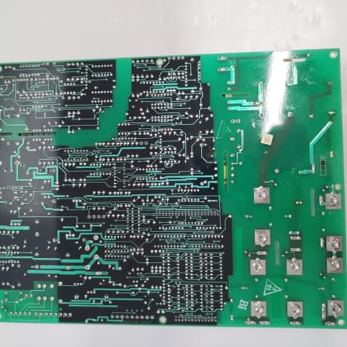
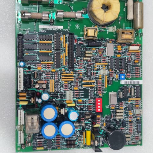
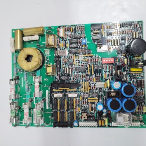
This GE 531X307LTBACG1 is a specialized logic and timing controller for the DC-300 and AC-300 drive platforms. The “LTB” designation identifies this board as a logic and timing controller—a dedicated module for applications requiring precise timing, high-speed counting, and pulse train generation. This board is designed for motion control, registration, and high-speed sequencing tasks.
The board features 16 digital I/O points, 8 high-speed counter/timer channels, and dual serial ports (RS-232 and RS-422/485). The onboard co-processor handles all timing functions independently from the main drive CPU, ensuring deterministic performance. The high-speed counter/timer channels can operate as up/down counters, frequency meters, pulse width modulators, or single-shot timers with microsecond resolution. This board is essential for packaging lines, cut-to-length applications, flying shears, and other applications requiring precise timing control.
Key Technical Specifications
| Parameter | Value |
|---|---|
| Manufacturer | GE (General Electric) |
| Model Number | 531X307LTBACG1 |
| Product Type | Logic and Timing Controller Board |
| Serial Ports | 2 (RS-232, RS-422/485) |
| Baud Rate | 300 to 38,400 bps |
| Digital I/O | 16 configurable inputs/outputs (24 VDC) |
| Output Drive | 0.5 A per digital output channel |
| Counter/Timer Channels | 8 independent channels |
| Counter Resolution | 16-bit (0-65,535 counts) |
| Timer Resolution | 1 µs |
| Max Counter Frequency | 100 kHz |
| Timer Modes | Up/down count, frequency measurement, PWM, single-shot, continuous |
| Co-Processor | Dedicated timing and logic processor |
| Protocol Support | GE proprietary, Modbus RTU |
| Isolation | 2500 V (opto-isolated I/O, transformer-isolated serial) |
| Communication | 50-pin ribbon cable to main regulator board |
| Operating Temperature | 0 to +55 °C |
| Storage Temperature | -40 to +85 °C |
| Board Dimensions | 12.7 in x 6.0 in (approx) |
Key Selling Points & Differentiators
- 8 High-Speed Counter/Timer Channels: Provides independent timing and counting functions with 1 µs resolution. Supports multiple modes: up/down counter, frequency measurement, PWM output, single-shot, and continuous timing.
- Dedicated Timing Co-Processor: Offloads all timing functions from the main drive CPU. The timing loops run independently of the motor control loops, ensuring deterministic performance even under heavy drive loads.
- Versatile Timing Modes: Each channel can be independently configured for different timing modes. Use one channel for PWM speed reference, another for registration pulse counting, and another for cycle timing—all on the same board.
- Quantified Testing Protocol: We test each counter/timer channel with a precision function generator. We verify counter accuracy to 0.01% and timer resolution to within 1 µs. Each board runs for 8 hours with all channels active.
- Warranty & Support: 2-year functional warranty. We include a comprehensive timing and counting configuration guide with application examples for common motion control tasks.
Frequently Asked Questions (FAQ)
Q1: What is the difference between the LTBACG1 and the standard LCC series boards?
A: The LCC series boards have analog and digital I/O with serial communication. The LTB series boards have dedicated high-speed counter/timer channels in addition to digital I/O and serial communication. The LTB board is for applications requiring precise timing and counting, such as registration control, speed measurement, and pulse train generation. The LCC boards are for general-purpose logic and analog control.
Q2: What are the typical applications for the LTB board?
A: The LTB board is used in packaging lines (registration control), cut-to-length applications (length measurement and cutting timing), flying shears (position/speed synchronization), labeling machines (mark sensor timing), and any application requiring high-speed counting or precise interval timing. It is also used for speed measurement (frequency mode) and PWM output for proportional control of valves or heaters.
Q3: Can the counter/timer channels be used as outputs for pulse generation?
A: Yes, the channels can be configured as PWM outputs or pulse train generators. The PWM output frequency can be set up to 100 kHz with variable duty cycle. This is useful for controlling proportional valves, heaters with solid-state relays, or generating speed reference pulses for other drives. The pulse train mode can generate up to 100 kHz square wave signals with variable frequency.
Q4: What is the maximum frequency for the counter inputs?
A: The counter inputs are rated for a maximum frequency of 100 kHz (100,000 pulses per second). The inputs are opto-isolated and accept 24 VDC signals. For higher frequencies, you would need a dedicated high-speed counter module. Do not exceed 100 kHz—the input circuit will saturate and produce incorrect counts. We have seen customers try to count encoder pulses at 200 kHz and get unreliable results.
Q5: Does this board support quadrature encoder inputs?
A: No. The counter/timer channels are single-ended inputs—they count pulses on a single input line. They do not support quadrature (A/B) decoding or direction counting from quadrature signals. For quadrature encoder support, you need the MCPA series motion control boards. The LTB board is for simple pulse counting and timing tasks.
Q6: Can the counter/timer channels be synchronized with each other?
A: Yes, the channels can be synchronized via software. You can start all channels simultaneously or trigger one channel from another. This is useful for applications requiring coordinated timing—for example, starting a timer when a counter reaches a preset value. The synchronization is handled by the co-processor with sub-microsecond accuracy.
Q7: Does this board support Modbus RTU for accessing the counter/timer data?
A: Yes, the counter/timer data is accessible via Modbus RTU over the RS-485 port. The counter values, timer status, and configuration registers are mapped to holding registers. This allows a PLC or SCADA system to read counts and timer values and change configurations on the fly. We provide the complete register map in our documentation.
Q8: What is the resolution of the PWM output?
A: The PWM output has a 16-bit duty cycle resolution (0 to 65,535 steps). The frequency can be set from 0.1 Hz to 100 kHz. The PWM output voltage level is 24 VDC (sourcing) at 0.5 A maximum. This is suitable for driving proportional valves with PWM inputs. The PWM output is also useful for controlling DC motor speed with an external H-bridge driver. The frequency stability is ±0.1% over temperature.
Q9: Is the LTBACG1 still in production?
A: No, this board is discontinued. GE produced the LTB series in limited quantities for motion applications. We have a limited stock of new surplus units. Used pulls are often damaged due to the sensitive counter/timer input circuitry. We recommend securing a spare if your application relies on the high-speed timing features. Once our stock is sold, this board will be difficult to source.
Q10: Can I use this board as a direct replacement for an LCC board in an existing system?
A: Physically, yes—the same dimensions, mounting holes, and 50-pin ribbon connector. However, the terminal block wiring is different because of the counter/timer channels. The LTB board has dedicated counter/timer input terminals that the LCC boards do not have. You would need to rewire the terminal connections. Also, the drive parameters for accessing the counter/timer functions are different. We provide a parameter configuration guide and a terminal block transition diagram for upgrades from LCC boards.
PR0S0FT MVI56E-SIE
ABB SPAS011
FOXBORO FBM232
WESTINGHOUSE 5X00070G04
 Email: sales@plcfcs.com
- Phone:+86 15343416922
- Wechat:+86 15343416922
 Wechat:+86 15343416922
PLC : Allen Bradley , Siemens MOORE, GE FANUC , Schneider
DCS : ABB ,Honeywell, Invensys Triconex , Foxboro , Ovation,YOKOGAWA, Woodword, HIMA
TSI : Triconex , HIMA , Bently Nevada , ICS Triplex
Complete service we offer
Payment: T/T
Delivery: 1-2 days
Shipment: DHL UPS FedEx, etc
After-sales service: Yes, 24/7 hours