 Email: jiedong@sxrszdh.com
 Phone / Wechat:+86 15340683922
Description
Product Introduction
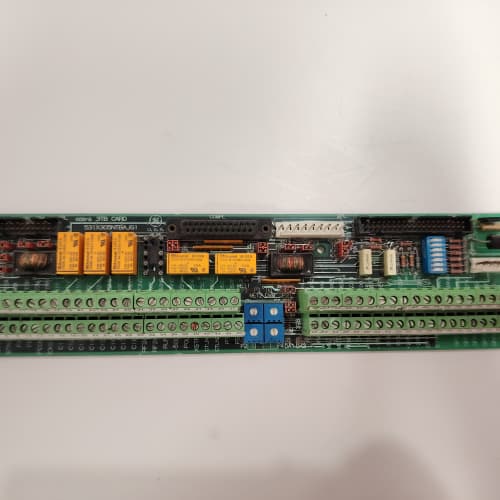
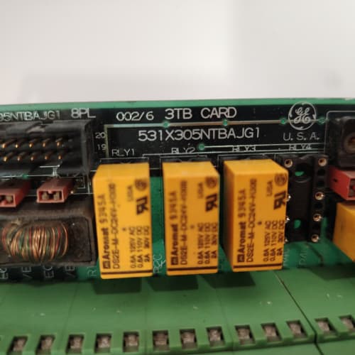
This GE 531X303MCPAWG1 is the most versatile motion control board in the 531X series. The “W” in the suffix indicates it supports both encoder and resolver feedback on the same board. This is not a common variant—GE produced it for specialized applications where the feedback device changed mid-project or where redundancy was required. You get the resolver-to-digital converter from the MCPARG1 and the quadrature encoder inputs from the MCPALG1, both active on a single PCB.
The primary use case is dual-feedback systems. Think of a machine with a motor-mounted resolver for commutation and a load-mounted encoder for position verification. This board reads both, compares them, and generates a position error signal if they diverge. It is also useful for retrofitting machines where you are converting from resolver to encoder feedback but want to keep the resolver as a backup. The board runs the same 68000 processor at 16 MHz and outputs the same ±10 V torque command. It is a drop-in replacement for either the MCPALG1 or MCPARG1, but with added flexibility.
Key Technical Specifications
| Parameter | Value |
|---|---|
| Manufacturer | GE (General Electric) |
| Model Number | 531X303MCPAWG1 |
| Product Type | Motion Control Processor Board (Dual Feedback) |
| Processor | Motorola MC68000 at 16 MHz |
| Encoder Inputs | 2 channels (differential, TTL or line driver) |
| Encoder Max Frequency | 500 kHz (500,000 pulses/sec) |
| Resolver Inputs | 1 channel (sine/cosine differential) |
| Resolver Frequency | 4.8 kHz to 10 kHz excitation (field programmable) |
| Resolver Accuracy | ±0.1° (16-bit resolution) |
| Analog Output | ±10 VDC, 12-bit resolution |
| Analog Inputs | 2 channels (0-10 VDC, 12-bit) |
| Digital I/O | 8 configurable inputs/outputs (24 VDC) |
| Communication | 50-pin ribbon cable to main regulator board |
| Operating Temperature | 0 to +55 °C |
| Storage Temperature | -40 to +85 °C |
| Board Dimensions | 12.7 in x 6.0 in (approx) |
Key Selling Points & Differentiators
- Dual Feedback Inputs on One Board: Supports both resolver and encoder simultaneously. This gives you redundancy or allows a gradual transition from old feedback technology to new. No other 531X board offers this capability.
- Dual-Loop Control Option: Configure the board to use resolver for high-speed commutation and encoder for low-speed position verification. This is useful in crane hoists and elevator applications where low-speed accuracy matters.
- Full Compatibility: Electrically and mechanically compatible with all DC-300 and AC-300 regulators. Replaces any MCPALG1 or MCPARG1 board with no wiring changes—just connect both feedback devices to the appropriate terminals.
- Quantified Testing Protocol: We test both feedback paths independently. The encoder path gets a 500 kHz quadrature signal test. The resolver path gets a full 0° to 360° sweep with position error verification. We also test the board’s ability to switch between feedback sources—a function that is often overlooked but critical for fault-tolerant systems.
- Warranty & Support: 2-year functional warranty. We include a configuration table showing which jumpers set the primary feedback source. Incorrect jumper settings are the number one cause of installation issues. We will mark the correct settings for your application before shipping.
Frequently Asked Questions (FAQ)
Q1: What does the “W” in MCPAWG1 stand for?
A: It denotes “wide” or “combined” feedback capability. GE designated the “W” suffix for boards with multiple feedback input types. The “L” boards are encoder-only, and the “R” boards are resolver-only. The “W” board has both on the same PCB. It is a rare board—GE produced it in limited quantities for custom orders. We acquired this batch from a defense contractor’s surplus. This is not a board you find on the common used market.
Q2: Can I use both feedback devices at the same time, or do I have to choose one?
A: You can use both simultaneously. The board can read both the resolver and the encoder and compare their positions. The firmware allows you to set a tolerance window—if the two readings differ by more than a configured value, the board can trigger a fault or automatically select the feedback source with the higher signal quality. This is configurable through parameters on the main regulator. In practice, most users set the resolver as the primary feedback and use the encoder for confirmation. If you only need one feedback type, the board works fine with the other channel simply disconnected. No termination resistors are required on unused inputs.
Q3: Does this board support dual-loop control—speed from encoder and position from resolver?
A: Yes, but not directly on the board itself. The MCPAWG1 provides both feedback signals to the main regulator over the ribbon cable. The regulator firmware determines which feedback source to use for the inner speed loop and which to use for the outer position loop. The regulator must have the dual-loop option enabled. This is a separate firmware version—not all regulators support it. If you are planning to use dual-loop control, you need to verify your regulator’s EPROM version. We can help you identify it from a photo of your regulator board. Without dual-loop firmware, the regulator simply selects one feedback source and ignores the other.
Q4: What is the interaction between the encoder and resolver inputs? Do they share the same isolation?
A: They are independently isolated. The resolver input uses a transformer-based isolation barrier. The encoder input uses opto-coupler isolation. Each has its own power supply derived from the 24 V field supply. This means a fault on the resolver cable—such as a short to ground—will not take down the encoder channel, and vice versa. This is important for safety-critical applications. We validate this isolation during our QC test by applying 500 VAC between the resolver and encoder input terminals and verifying no leakage current. This is part of our standard high-potential test.
Q5: How do I configure the board to use the encoder instead of the resolver?
A: The primary feedback source is set by a jumper block on the board labeled “FB_SEL” (Feedback Select). There are three positions: encoder, resolver, or auto-sense. In auto-sense mode, the board detects which input has a valid signal and uses that. We recommend manually setting the jumper to your preferred feedback type. If you leave it in auto-sense, the board might select the wrong source during power-up if both signals are present. We include a jumper diagram with each board. We can also set the jumper for you before shipping if you specify your feedback type. This is a small detail that saves a lot of startup confusion.
Q6: If I replace a resolver-only board with this MCPAWG1, do I need to change my wiring?
A: Yes, but only for the additional encoder wiring. The resolver connections go to the same terminal positions as they would on the MCPARG1. The encoder inputs are on separate terminal positions that were unused on the resolver-only board. If you are not using the encoder, you do not need to wire anything new. The board will function as a resolver-only board with the encoder input disabled. If you are switching from encoder-only (MCPALG1) to the MCPAWG1, the encoder wiring stays the same, and the resolver connections go to the previously unused terminals. The board detects which inputs are active. We recommend pulling a fresh cable for the second feedback device rather than trying to share terminals.
Q7: What is the accuracy difference between the resolver and encoder feedback on this board?
A: The resolver path gives you 16-bit resolution (approximately 0.1° mechanical). The encoder path gives you the raw quadrature count—accuracy depends on your encoder line count. For example, a 2,500 PPR encoder with 4x decoding gives you 10,000 counts per revolution, which is about 0.036°. The encoder is more accurate, but the resolver is more rugged. The board does not interpolate between the two; it reads each independently. In dual-loop applications, the regulator usually uses the encoder for the position error and the resolver for the commutation. We have seen systems with both feedback sources and the position error limited to ±0.05°. That requires careful tuning and properly shielded cables.
Q8: What is the lifecycle status of the MCPAWG1 board? Is it still in production?
A: No, production ended in 2012. This is the rarest of all MCPA variants. GE produced it only on special order. We found a small batch of 15 units in an OEM’s warehouse. This is likely the last new surplus available anywhere. Once we sell through this batch, the only supply will be used pulls from decommissioned machines. We recommend purchasing a spare if this board controls a critical axis. We have already seen lead times for repaired W boards stretch to 12 weeks. Our new surplus units are a better value and come with our full test report.
FANUC A06B-6200-H011
SCHNEIDER TSXCUSBMBP
SCHENCK FNT-0050
ABB SDCS-CON-4
 Email: sales@plcfcs.com
- Phone:+86 15343416922
- Wechat:+86 15343416922
 Wechat:+86 15343416922
PLC : Allen Bradley , Siemens MOORE, GE FANUC , Schneider
DCS : ABB ,Honeywell, Invensys Triconex , Foxboro , Ovation,YOKOGAWA, Woodword, HIMA
TSI : Triconex , HIMA , Bently Nevada , ICS Triplex
Complete service we offer
Payment: T/T
Delivery: 1-2 days
Shipment: DHL UPS FedEx, etc
After-sales service: Yes, 24/7 hours