 Email: jiedong@sxrszdh.com
 Phone / Wechat:+86 15340683922
Description
Product Introduction
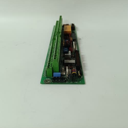
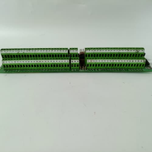
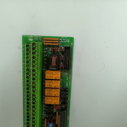
This GE 531X303MCPARG1 is a motion control processor board specifically configured for resolver-based feedback. It is nearly identical to the MCPALG1, but replaces the encoder input circuitry with a resolver-to-digital converter. This board is designed for applications where resolvers are the preferred feedback device—typically in high-vibration environments, oil and coolant exposure, or high-temperature zones where optical encoders fail.
The board uses a 16-bit resolver-to-digital converter to decode the sine and cosine signals from the resolver. It tracks rotor position at speeds up to 10,000 RPM with an accuracy of ±0.1°. The processor then closes the position loop and outputs a ±10 V analog torque command to the drive. This board is common in forging presses, extrusions, and gear-driven spindle applications. If your machine uses resolvers from manufacturers like Tamagawa, Harowe, or Litton, this is the correct board to interface them with your GE drive.
Key Technical Specifications
| Parameter | Value |
|---|---|
| Manufacturer | GE (General Electric) |
| Model Number | 531X303MCPARG1 |
| Product Type | Motion Control Processor Board (Resolver) |
| Processor | Motorola MC68000 at 16 MHz |
| Resolver Inputs | 1 channel (sine/cosine differential) |
| Resolver Frequency | 4.8 kHz to 10 kHz excitation (field programmable) |
| Resolver Voltage | 2.5 VAC RMS nominal (1.0-5.0 VAC range) |
| Resolver Accuracy | ±0.1° (16-bit resolution) |
| Max Tracking Speed | 10,000 RPM (adjustable) |
| Analog Output | ±10 VDC, 12-bit resolution |
| Analog Inputs | 2 channels (0-10 VDC, 12-bit) |
| Digital I/O | 8 configurable inputs/outputs (24 VDC) |
| Communication | 50-pin ribbon cable to main regulator board |
| Operating Temperature | 0 to +55 °C |
| Storage Temperature | -40 to +85 °C |
| Board Dimensions | 12.7 in x 6.0 in (approx) |
Key Selling Points & Differentiators
- Resolver-Based Feedback for Harsh Environments: Resolvers are more rugged than optical encoders. They handle shock, vibration, moisture, and extreme temperatures without losing position. This board gives you that capability on a DC-300 or AC-300 drive.
- 16-Bit Resolver-to-Digital Conversion: Provides 0.1° accuracy at 10,000 RPM. This is sufficient for most industrial positioning and speed control applications. The conversion is updated every 100 µs, giving you a 10 kHz velocity loop update rate.
- Built-In Resolver Excitation: The board generates the excitation signal—no external resolver driver required. The frequency and voltage are adjustable through onboard jumpers and EPROM settings. We can verify the excitation matches your resolver spec before shipping.
- Full Functional Test on Live Drive: We test each MCPARG1 on a DC-300 test stand with an actual resolver simulator. We verify the board tracks position at speeds from 1 RPM to 10,000 RPM. We check the analog output for linearity and the digital I/O for correct state. A simple power-on test does not catch resolver circuit issues; our test does.
- Warranty & Support: 2-year functional warranty. We include a resolver wiring guide that shows the correct pinout for the most common resolver manufacturers. Most resolver wiring errors come from mixing up sine and cosine pairs—our guide prevents that.
Frequently Asked Questions (FAQ)
Q1: What is the difference between the MCPARG1 and the MCPALG1?
A: The “R” in MCPARG1 stands for resolver. The “L” in MCPALG1 stands for encoder (line driver). The two boards are physically identical except for the feedback input stage. The MCPARG1 has a resolver-to-digital converter and excitation circuitry. The MCPALG1 has quadrature encoder receiver chips. You cannot swap one for the other without changing the feedback device. If your machine uses resolvers, you need the MCPARG1. If it uses incremental encoders, you need the MCPALG1.
Q2: What resolver voltage and frequency does this board support?
A: The board supports excitation voltages from 1.0 VAC to 5.0 VAC RMS and frequencies from 4.8 kHz to 10 kHz. The most common setting is 2.5 VAC at 4.8 kHz. You configure the excitation through a combination of jumpers on the board and EPROM constants. We check the jumper configuration against the resolver model you specify. If you do not know your resolver spec, we can help you identify it from the resolver part number. We carry a cross-reference sheet for Tamagawa, Harowe, and Litton resolvers. We have also seen cases where the resolver excitation voltage was set incorrectly and the board could not acquire lock. We double-check this before shipping.
Q3: What is the maximum cable length for the resolver wiring?
A: GE recommends a maximum of 300 feet (90 meters) for resolver cables. The cable must be shielded twisted-pair (four pairs minimum: sine, cosine, and excitation). The shield should be grounded at the drive end only. We have seen installations at 500 feet work reliably with high-quality cable and proper grounding, but we do not guarantee performance beyond the GE specification. The bigger issue is capacitance on the excitation wires—excessive capacitance can cause voltage drop and phase shift. If you are running more than 200 feet, we suggest using a separate excitation buffer amplifier or moving the drive closer to the motor.
Q4: Does this board support commutation of a brushless motor directly from resolver feedback?
A: Yes, but with a catch. The board calculates the rotor position angle from the resolver and outputs it to the main regulator. The regulator must have the brushless motor commutation option enabled and configured for resolver feedback. This is a separate firmware option on the regulator board. If your regulator does not have brushless commutation firmware, the MCPARG1 will output position data, but the regulator will not use it for commutation. In that case, you are only using the board for velocity feedback. If you need full commutation, check your regulator firmware part number. We can verify this for you if you send us a photo of the regulator board’s EPROM label.
Q5: How do you test the resolver input during your QC process?
A: We use a resolver simulator that generates sine/cosine signals at known angles. We sweep the simulated angle from 0° to 360° and monitor the board’s output position over the ribbon cable. We verify that the position tracks accurately within ±0.15° at all angles. We also run a velocity test at 5,000 RPM and check for loss of tracking. If the board loses lock or the position error exceeds the limit, we reject it. We repeat this test after a 2-hour thermal soak to ensure no drift. The test report is available on request.
Q6: I am replacing an MCPARG0 board with an MCPARG1. Are there any compatibility issues?
A: The hardware is compatible. The mounting holes, 50-pin connector, and terminal blocks are identical. However, the G1 firmware adds electronic gearing and registration functions. These are additional features—they should not affect your existing motion parameters. That said, the G1 board might have different default scaling constants. In our experience, the position loop gain needs to be re-tuned after any motion board swap. You should also verify the resolver excitation frequency matches your resolver spec. We have seen G0 boards set to 4.8 kHz and G1 boards defaulted to 10 kHz, which caused the resolver to overheat. Check the jumpers before power-up. We provide a jumper map with every board.
Q7: What happens if the resolver feedback signal is lost during operation?
A: The board has a loss-of-signal detection circuit. If the sine or cosine signal drops below a set threshold, the board will trigger a fault on the digital I/O output designated as the “resolver fault” channel. This fault signal goes to the main regulator, which will shut down the drive and display a feedback loss alarm. The fault is latched and requires a power cycle to clear. In our experience, this often happens due to a broken wire in the resolver cable. We recommend using a cable break monitor (available separately) if your resolver cable is subject to flexing. The board itself does not fail from loss of feedback—it just reports the condition and stops commanding current. This prevents motor runaway.
ABB CI856K01
SIEMENS 6SY7000-0AD05
SIEMENS 6SE6440-2AD27-5CA1
 Email: sales@plcfcs.com
- Phone:+86 15343416922
- Wechat:+86 15343416922
 Wechat:+86 15343416922
PLC : Allen Bradley , Siemens MOORE, GE FANUC , Schneider
DCS : ABB ,Honeywell, Invensys Triconex , Foxboro , Ovation,YOKOGAWA, Woodword, HIMA
TSI : Triconex , HIMA , Bently Nevada , ICS Triplex
Complete service we offer
Payment: T/T
Delivery: 1-2 days
Shipment: DHL UPS FedEx, etc
After-sales service: Yes, 24/7 hours