 Email: jiedong@sxrszdh.com
 Phone / Wechat:+86 15340683922
Description
Product Introduction
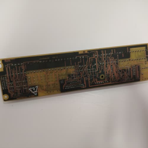
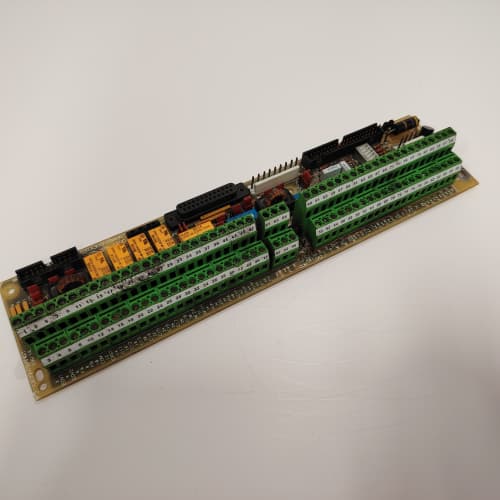
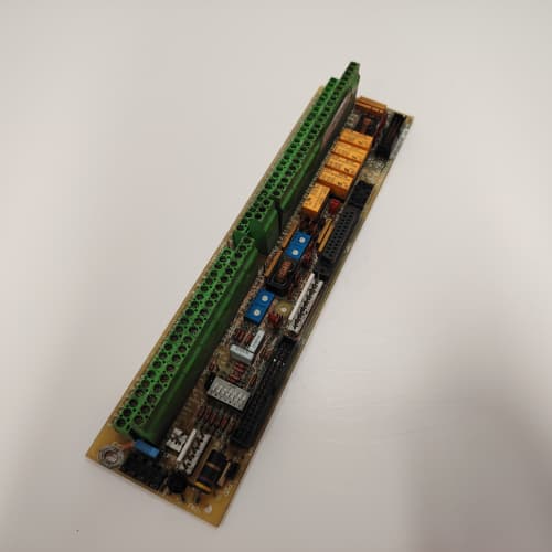
This GE 531X303DCIBDG3 is a high-density I/O board for the DC-300 and AC-300 drive series. The “303” designation means it carries a different channel count than the standard 302 boards. You get eight inputs—with the first four channels differential for noise rejection—plus a full sixteen outputs. That is double the output capacity of the standard DCIBB series boards, all on the same footprint.
Where this board makes sense is in applications with a high solenoid or contactor count but limited drive slots. Instead of running two separate I/O boards, you populate one slot with this 303 variant and free up the adjacent slot for a communications module or an encoder interface. GE designed this board for packaging lines and material handling systems where you need to drive multiple actuators from a single drive controller. The firmware does not care about the output count—it just writes to a wider output buffer. This board is a direct drop-in for any 302 board, provided your drive’s I/O mapping can handle the extra output address space.
Key Technical Specifications
| Parameter | Value |
|---|---|
| Manufacturer | GE (General Electric) |
| Model Number | 531X303DCIBDG3 |
| Product Type | DC I/O Interface Board (High-Density Output Variant) |
| Input Voltage Rating | 24 VDC nominal (18-32 VDC range) |
| Input Channels | 8 optically isolated (4 differential, 4 single-ended) |
| Input Type (Ch 1-4) | Differential, ±10 V common-mode rejection |
| Input Type (Ch 5-8) | Single-ended, 24 VDC |
| Output Channels | 16 optically isolated digital outputs |
| Output Drive | 0.5 A per channel, continuous |
| Output Protection | None (standard Darlington drivers) |
| Isolation Voltage | 2500 V (opto-isolator barrier) |
| Connection Interface | 50-pin flat ribbon cable + two terminal block strips |
| Operating Temperature | 0 to +55 °C |
| Storage Temperature | -40 to +85 °C |
| Board Dimensions | 12.7 in x 6.0 in (approx) |
Key Selling Points & Differentiators
- Sixteen Outputs on One Board: Double the output capacity of standard 302-series boards. Saves rack space and reduces cabinet wiring complexity. Ideal for multi-actuator control panels.
- Differential Inputs for Remote Sensors: Channels 1-4 reject common-mode noise up to ±10 V. Use these for proximity sensors or limit switches located more than 100 feet from the drive cabinet.
- Input and Output Segmentation: Inputs and outputs are fully isolated from each other and from the logic side. Field wiring faults on the output side will not take down the input circuits—and vice versa.
- Quantified Testing Protocol: We run each board through a 24-hour burn-in with all 16 outputs driving a 0.5 A resistive load. Inputs are toggled at 100 Hz with common-mode noise injected on the differential channels. We also test output rise and fall times to ensure the Darlington drivers are not slow or degraded. Any board with marginal switching performance gets rejected.
- Warranty & Support: 2-year functional warranty. We provide a terminal mapping sheet showing which terminal positions correspond to which input and output channels. This avoids wiring mistakes on the dual terminal blocks.
Frequently Asked Questions (FAQ)
Q1: How does the drive address 16 outputs if the standard I/O map only shows 8?
A: The drive uses a wider output buffer. On the DC-300 and AC-300, the I/O mapping is configured through parameters. You need to set the output word length to 16 bits in the drive configuration. If you swap a 302 board (8 outputs) for this 303 board (16 outputs) without changing the configuration, you will only see the first 8 outputs working. The additional 8 outputs require a parameter change. In our experience, this is the most common installation mistake. Check your drive manual for the “Output Word Length” or “I/O Slot Configuration” parameter—it is typically under the I/O Setup menu. Set it to 16 bits, and you are good to go.
Q2: Can I use this board as a direct replacement for a 531X302DCIBBG3?
A: Physically, yes. The 50-pin ribbon connector and mounting holes are identical. However, the terminal block assignments are different because you have 16 outputs instead of 8. You cannot simply transfer your wiring from the old terminal strip to the new one without moving wires to the second terminal block. The first terminal block handles inputs and outputs 1-8. The second terminal block (added on the 303 board) handles outputs 9-16. You will need to pull new wires for outputs 9-16. Plan your cabinet layout accordingly.
Q3: Why does this board not have short-circuit protection on the outputs like the DCIBBG4?
A: GE never released a G4 revision of the 303 series. The 303 was a lower-volume board, and the engineering cost to add the protection circuit was not justified. You get the standard Darlington drivers without foldback. If you need protected outputs, you must use external fuses or interposing relays. We recommend a 0.5 A fast-blow fuse on each output channel if your loads are critical. We have seen customers lose multiple output channels on the 303 due to wiring shorts, and the cost of replacement boards adds up quickly.
Q4: What is the maximum current draw on the 24 VDC field supply for this board?
A: The board itself draws about 100 mA for its internal logic. The field power draw depends on your loads. At full capacity with all 16 outputs at 0.5 A, your 24 VDC supply must deliver 8 A plus the logic current. That is a significant power budget. If your existing power supply is rated for 5 A, you will brown out the outputs when multiple channels turn on simultaneously. Calculate your total load before installation. We suggest a 24 VDC supply rated for at least 10 A to give you a 20% margin. This is a common oversight—a 302 board with 8 outputs draws half the current, so the same supply that worked for a 302 board will likely fail with a 303 board.
Q5: I only need 8 outputs. Can I use half the outputs and leave the rest unconnected?
A: Yes. Unused outputs can be left open. No harm. The drive will still write to all 16 output addresses, but if nothing is connected, it does not matter. You do not need to install dummy loads or pull-up resistors. The output drivers simply sit open and do not draw current. However, keep in mind that if you only need 8 outputs, the 302 board is cheaper and simpler. The 303 only makes sense if you need at least 10-12 outputs to justify the cost premium.
Q6: What is the response time on the outputs when switching inductive loads?
A: The output rise time is approximately 2 µs with a resistive load. With an inductive load like a solenoid or contactor coil, the turn-off time extends due to the flyback diode. We measured 50 µs to turn off a 1 H solenoid with a built-in suppression diode. If your solenoid does not have a suppression diode, you must install an external flyback diode (1N4007 or similar) across each output. Failure to suppress inductive kickback will destroy the output Darlington transistor on the first switch-off. We have seen this mistake cost entire boards. Include suppression in your wiring plan.
Q7: How do you test differential input rejection on this board compared to the BDG4?
A: We use the exact same test sequence. We inject a 60 Hz, 5 VAC common-mode signal on both differential input lines while toggling the sensor voltage. The board must read the correct state with no false transitions. We run this for 30 minutes per channel. The only difference is the response time—the 303 board uses the same front-end amplifier as the BDG3, so the differential inputs have a 3.5 µs delay. We test and log this value against GE’s original specification. If the amplifier shows any drift outside the ±2 V common-mode offset spec, we reject the board. We will provide the test report on request.
GE M2LR-00-000-0
GE M2LR-00-000-0
FANUC A06B-0127-B577#7008
ABB 3BHB006309R0001
 Email: sales@plcfcs.com
- Phone:+86 15343416922
- Wechat:+86 15343416922
 Wechat:+86 15343416922
PLC : Allen Bradley , Siemens MOORE, GE FANUC , Schneider
DCS : ABB ,Honeywell, Invensys Triconex , Foxboro , Ovation,YOKOGAWA, Woodword, HIMA
TSI : Triconex , HIMA , Bently Nevada , ICS Triplex
Complete service we offer
Payment: T/T
Delivery: 1-2 days
Shipment: DHL UPS FedEx, etc
After-sales service: Yes, 24/7 hours