 Email: jiedong@sxrszdh.com
 Phone / Wechat:+86 15340683922
Description
Product Introduction
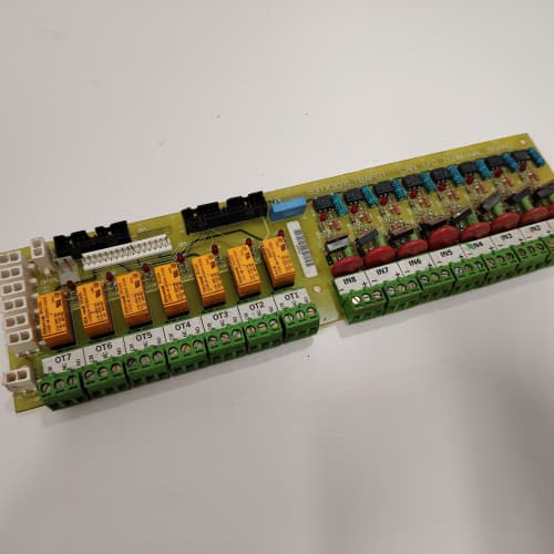
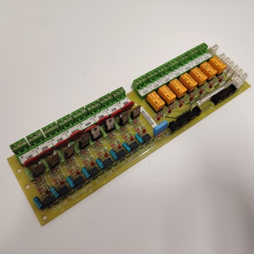
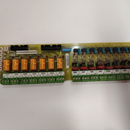
This GE 531X302DCIBDG3 is a specialized I/O termination board for the DC-300 and AC-300 drive families. Unlike the standard DCIBB series, the “D” in the suffix indicates differential inputs on the first four channels. This is critical when you have long field wiring runs (over 100 feet) or installations with significant electrical noise from VFDs, welding equipment, or heavy motor starters.
The differential inputs give you common-mode rejection of up to ±10 V. That means if your sensor’s return wire picks up stray voltage from a nearby 480 VAC cable, the board ignores it and reads only the true signal difference. We have seen this board installed in steel mills and automotive stamping plants where standard single-ended inputs would chatter or false-trip constantly. It is not an everyday replacement, but when you need it, nothing else works reliably.
Key Technical Specifications
| Parameter | Value |
|---|---|
| Manufacturer | GE (General Electric) |
| Model Number | 531X302DCIBDG3 |
| Product Type | DC I/O Interface Board (Differential Input Variant) |
| Input Voltage Rating | 24 VDC nominal (18-32 VDC range) |
| Input Channels | 8 optically isolated digital inputs (4 differential, 4 single-ended) |
| Input Type (Ch 1-4) | Differential, isolated, ±10 V common-mode rejection |
| Input Type (Ch 5-8) | Single-ended, 24 VDC |
| Output Channels | 8 optically isolated digital outputs |
| Output Drive | 0.5 A per channel, continuous |
| Isolation Voltage | 2500 V (opto-isolator barrier) |
| Connection Interface | 50-pin flat ribbon cable + terminal block strip |
| Operating Temperature | 0 to +55 °C |
| Storage Temperature | -40 to +85 °C |
| Board Dimensions | 12.7 in x 6.0 in (approx) |
Key Selling Points & Differentiators
- Differential Inputs for Noisy Environments: Channels 1 through 4 are true differential inputs with 10 V common-mode rejection. This eliminates false triggers on long cable runs. Standard single-ended boards will pick up noise; this board rejects it.
- Mixed Input Configuration: You get both types on one board. Use the differential channels for your remote proximity sensors or encoders, and use the single-ended channels for local pushbuttons or selector switches in the cabinet. No need for separate signal conditioners.
- OEM Traceability: New surplus from GE’s final production batch. We track the date code and factory test stamp on the board edge. No third-party rebuilds, no reworked solder joints.
- Quantified Testing Protocol: Each board undergoes a full I/O test with a 50-foot simulated cable run. We inject common-mode noise at ±5 V on the differential inputs while verifying the channel toggles cleanly. Outputs run at 0.5 A for 24 hours. We do not ship boards with marginal opto-coupler rise times.
- Warranty & Support: 2-year warranty. We also provide a one-page wiring note showing the correct termination for differential sensors (three-wire vs. two-wire, shielded twisted-pair, drain wire grounding). This avoids the most common field installation mistakes.
Frequently Asked Questions (FAQ)
Q1: What is the difference between this “BDG3” and the standard “BBG3” board?
A: The “BD” suffix designates differential inputs on the first four channels. The standard “BB” board has all eight inputs single-ended. If you are wiring to a PNP proximity sensor 150 feet away from the drive cabinet, the single-ended board will likely see noise spikes and false-trigger. The differential board compares the signal wire against its dedicated return wire, cancelling out the noise. Physically, the BD board has an extra input conditioning IC near the terminal block. It is a drop-in replacement for the BB board, but you must wire the differential channels as a twisted pair.
Q2: Can I use the differential inputs with a standard two-wire proximity sensor?
A: No. Two-wire sensors do not provide a separate return for the differential pair. For differential inputs, you need a three-wire sensor (power, signal, and return) or a four-wire device with separate signal and return lines. If you only have two-wire sensors, use channels 5-8 (single-ended). If you need more than four differential channels, you will need a second BD board or a separate signal isolator. We recommend using Belden 8760 twisted-pair shielded cable for differential runs—it makes a measurable difference on runs over 200 feet.
Q3: I have an older DC-300 drive that shows input chatter on channel 1. Can I swap my existing BB board for this BD board to fix it?
A: Yes, and this is exactly why GE released the BD version. The board is mechanically and electrically compatible. However, you must rewire the terminal block for the differential channels. The terminal pinout is different—pins 1-4 on the terminal strip now have both a signal and a return connection. Do not just plug the board in and leave the existing wiring; you will need to pull a separate return wire for each differential sensor. We can send you the terminal wiring diagram before you order so you can confirm you have enough spare conductors in your cable.
Q4: What is the common-mode voltage range I can expect on the differential inputs?
A: The specification is ±10 VDC common-mode at the input terminals. That means if your signal return wire is floating at +5 V relative to the drive ground, the board will still read the difference correctly. We tested this on our bench—we applied +8 V to the return line and 24 V to the signal line, and the input read “ON” cleanly. Beyond ±10 V, the input protection diodes start to clamp, and you risk damaging the input circuit. If your installation has more than 10 V of ground shift, you need an external isolation amplifier before this board.
Q5: Will this board work with the newer AC-300 drives running firmware version 8.x?
A: Yes, we have validated this. The I/O backplane on the AC-300 uses the same 50-pin ribbon connector and the same 24 V logic levels. Firmware does not distinguish between the BB and BD board types. The drive just reads the input buffer register regardless of the front-end conditioning. We have a customer running three BD boards in an AC-300 on a conveyor line with no communication errors. No configuration change is required in the drive parameters.
Q6: What is your test procedure for the differential input rejection?
A: We use a function generator to inject a 60 Hz, 5 VAC common-mode signal onto both input lines while we toggle the sensor voltage. The board must read the correct state with no chatter. We run this test for 30 minutes per channel. We also test for response time—the differential inputs have a slightly longer filter (approx 3 µs) than the single-ended channels (approx 2 µs) due to the front-end amplifier. We log both values and ensure they fall within GE’s original acceptance range. We will share the test report with you upon request.
Q7: Is the G3 suffix on this board compatible with the G4 suffix boards from the BB series?
A: Yes, and no. The G3 and G4 suffixes refer to revision levels within the same input type family. The G4 on the BB board added short-circuit protection on the outputs. The G3 on the BD board does not have short-circuit protection on the outputs. GE never released a G4 version of the BD differential board. So, if you need differential inputs and output short-circuit protection, you are out of luck—no such board exists. You would need to use a BDG3 for inputs and an external fuse block or interposing relay for output protection. Be aware of this limitation if your outputs drive critical solenoids.
A-B 1756-PAR2
BENTLY 3500/15-05-05-CN
GE IC693CPU374
Bently 3300/16
 Email: sales@plcfcs.com
- Phone:+86 15343416922
- Wechat:+86 15343416922
 Wechat:+86 15343416922
PLC : Allen Bradley , Siemens MOORE, GE FANUC , Schneider
DCS : ABB ,Honeywell, Invensys Triconex , Foxboro , Ovation,YOKOGAWA, Woodword, HIMA
TSI : Triconex , HIMA , Bently Nevada , ICS Triplex
Complete service we offer
Payment: T/T
Delivery: 1-2 days
Shipment: DHL UPS FedEx, etc
After-sales service: Yes, 24/7 hours