 Email: jiedong@sxrszdh.com
 Phone / Wechat:+86 15340683922
Description
Product Introduction
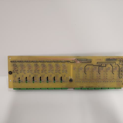
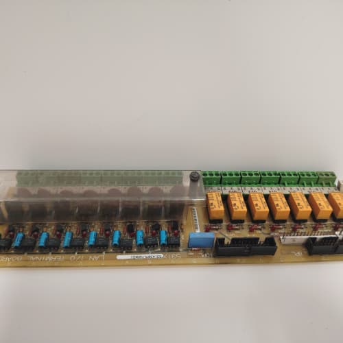
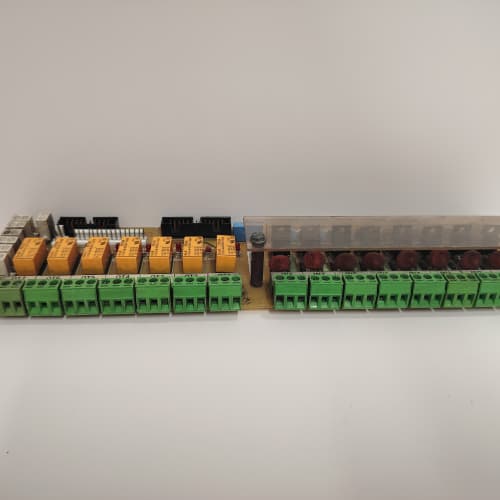
This GE 531X302DCIBBG4 is a later-revision I/O termination board designed for the DC-300 and AC-300 drive families. It performs the same core function as the G3 variant—translating 24 VDC field signals to the drive’s 5 V logic—but adds a critical upgrade: individual output short-circuit protection. You will find this board in cabinets requiring higher reliability for output channels driving contactors, solenoids, or indicator lamps.
The G4 revision is the final production version of this board series. GE introduced the short-circuit protection to address field failures where output transistors would blow from accidental wiring shorts. Instead of replacing the entire board, the protection circuit folds back and resets after the fault clears. This single feature can save you from an unscheduled shutdown and a service call. It is a drop-in replacement for earlier G1 through G3 boards, provided you have the space for the slightly taller heatsink on the output drivers.
Key Technical Specifications
| Parameter | Value |
|---|---|
| Manufacturer | GE (General Electric) |
| Model Number | 531X302DCIBBG4 |
| Product Type | DC I/O Interface Board |
| Input Voltage Rating | 24 VDC nominal (18-32 VDC range) |
| Input Channels | 8 optically isolated digital inputs |
| Output Channels | 8 optically isolated digital outputs |
| Output Drive | 0.5 A per channel, continuous |
| Output Protection | Short-circuit protected, auto-reset (foldback current limiting) |
| Isolation Voltage | 2500 V (opto-isolator barrier) |
| Connection Interface | 50-pin flat ribbon cable (main logic) + terminal block strip |
| Operating Temperature | 0 to +55 °C |
| Storage Temperature | -40 to +85 °C |
| Board Dimensions | 12.7 in x 6.0 in x 0.8 in (approx) |
Key Selling Points & Differentiators
- Short-Circuit Protected Outputs: The G4 adds foldback current limiting on all 8 outputs. If a field wire shorts to ground, the output current limits to 0.7 A and the channel protects itself. Remove the short, and the channel resumes normal operation. No blown drivers, no board replacement.
- Drop-In Backward Compatibility: Replaces any 531X302DCIBB series board (A, B, C, D, G1, G2, G3). The connector pinout and mounting holes are identical. You do not need to rewire the terminal strip or change the ribbon cable.
- OEM Stock, Traceable Sourcing: These are new surplus boards from GE’s final production run. We log the date code and board revision. No repaired traces, no counterfeit components.
- Quantified Testing Protocol: Every board undergoes a 24-hour burn-in with all inputs toggled at 1 kHz and all outputs driving a 0.5 A resistive load. We also short each output to ground for 5 seconds to verify the protection circuit engages and recovers correctly. We do not ship a board that fails any single test point.
- Warranty & Support: 2-year functional warranty. Includes free pre-shipment photo verification of the board and packaging. We will also email you a PDF of the terminal wiring diagram from the original GE manual so you can confirm your field connections before installation.
Frequently Asked Questions (FAQ)
Q1: What is the actual difference between the G3 and G4 versions?
A: The G4 has short-circuit protection on the output transistors. The G3 does not—it uses standard Darlington drivers that blow if shorted. GE added a current-sensing IC and a foldback circuit on the G4. The input side is identical. The G4 also has a slightly larger heatsink (about 0.2 inches taller) on the output driver array. Both boards are functionally interchangeable in the same slot.
Q2: Can I use a G4 to replace a G1 board that has a 50-pin ribbon cable with a keyed connector?
A: Yes. The 50-pin header is identical. However, some very early G1 boards used a shrouded header with a polarizing key. The G4 uses an unshrouded header but retains the same pinout. If your cable has the keyed shroud, it will still plug onto the G4 header. Just make sure pin 1 orientation matches—there is a small triangle marker on the board next to pin 1. Line up the red stripe on your ribbon cable to pin 1.
Q3: Does the G4 require a firmware update on the main regulator board to recognize it?
A: No. The main drive logic board sees this as a standard 8-in/8-out I/O board. There is no handshake or ID check. The regulator simply polls the input buffer and writes to the output latch. No firmware, no parameters. This is a straight hardware swap. We have tested this on DC-300 drives running firmware versions 4.x through 7.x without any issue.
Q4: The output short-circuit protection—does it limit current to 0.5 A or 0.7 A?
A: It kicks in around 0.7 A, but the foldback reduces the current to approximately 0.2 A during a sustained short. The output will not latch off permanently; it recovers automatically when the short is removed. In our bench tests, we shorted an output for 30 seconds, removed the short, and the output returned to full 0.5 A drive capability within 100 ms. This is a self-resetting protection, not a fuse or a one-time thermal trip.
Q5: What is the maximum switching frequency I can run on the outputs?
A: The output transistors are rated for 10 kHz maximum. However, the opto-isolators on the input side are faster—about 2 µs response time. For outputs driving contactors or solenoids, you are likely running at 1-2 Hz. If you need PWM output for a brake or a heater, keep it under 100 Hz to avoid overheating the output drivers. At 0.5 A continuous load and 100 Hz, the board temperature rises about 15 °C above ambient. We recommend staying below 50% duty cycle at 1 kHz for continuous operation.
Q6: Will this board work in an AC-300 drive, or is it strictly for DC-300?
A: Yes, it works in both. The DC-300 and AC-300 share the same I/O backplane connector and voltage levels. The AC-300 uses the same 24 VDC I/O standard. We have installed these G4 boards in AC-300 drives running paper mill winders and extruder lines. No modification needed. The mounting holes align with the drive chassis in both platforms.
Q7: How do you test the short-circuit protection before shipping?
A: We run a specific test sequence. After the 24-hour burn-in, we take each output, drive it to 0.5 A, then deliberately short it to ground through a 0.1-ohm shunt resistor. We monitor the current foldback to ensure it drops below 0.3 A within 50 µs. Then we remove the short and verify the channel returns to full current within 200 ms. We repeat this for all 8 outputs. If any channel fails to recover, the board goes to our repair bench for component-level troubleshooting. We never ship a board that has not passed this test.
ABB UGTMEM-01SB47S
A-B 1747-L551
HIMA F6217
 Email: sales@plcfcs.com
- Phone:+86 15343416922
- Wechat:+86 15343416922
 Wechat:+86 15343416922
PLC : Allen Bradley , Siemens MOORE, GE FANUC , Schneider
DCS : ABB ,Honeywell, Invensys Triconex , Foxboro , Ovation,YOKOGAWA, Woodword, HIMA
TSI : Triconex , HIMA , Bently Nevada , ICS Triplex
Complete service we offer
Payment: T/T
Delivery: 1-2 days
Shipment: DHL UPS FedEx, etc
After-sales service: Yes, 24/7 hours