 Email: jiedong@sxrszdh.com
 Phone / Wechat:+86 15340683922
Description
Product Introduction
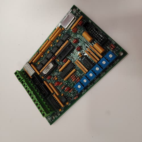
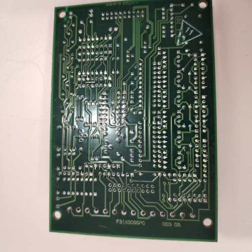
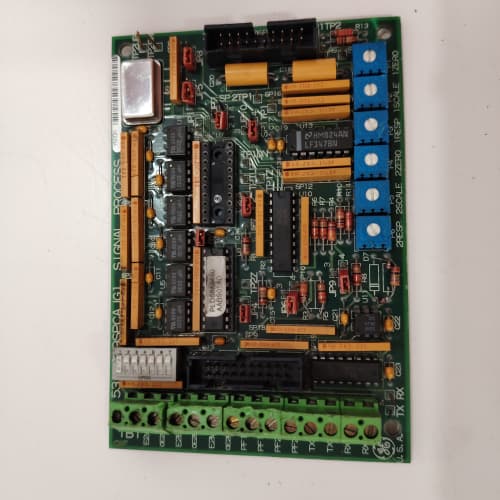
This GE 531X302DCIBBG3 is a replacement I/O termination board built for the DC-300 and AC-300 series drive platforms. It handles discrete field-device signal translation between your 24 VDC sensors, pushbuttons, and the drive’s internal control logic. You typically find this board mounted inside the drive cabinet, wired directly to the main regulator board via the 50-pin ribbon cable.
Where this board shines is its galvanic isolation. It separates your noisy 120 VAC field wiring from the sensitive 5 VDC logic side. Instead of replacing an entire drive chassis, you swap this board to restore I/O points lost to lightning strikes, short circuits, or terminal block damage. It is a targeted fix that cuts downtime from days to hours.
Key Technical Specifications
| Parameter | Value |
|---|---|
| Manufacturer | GE (General Electric) |
| Model Number | 531X302DCIBBG3 |
| Product Type | DC I/O Interface Board |
| Input Voltage Rating | 24 VDC nominal (18-32 VDC range) |
| Input Channels | 8 optically isolated digital inputs |
| Output Channels | 8 optically isolated digital outputs |
| Output Drive | 0.5 A per channel, continuous |
| Isolation Voltage | 2500 V (opto-isolator barrier) |
| Connection Interface | 50-pin flat ribbon cable (main logic) + terminal block strip |
| Operating Temperature | 0 to +55 °C |
| Storage Temperature | -40 to +85 °C |
| Board Dimensions | 12.7 in x 6.0 in (approx) |
Key Selling Points & Differentiators
- Hardened Isolation: Opto-isolators rated at 2500 V. This is not a simple buffer board. It protects your main control board from field wiring faults, which is the #1 failure point in older drive cabinets.
- OEM Stock, Not Rebuilds: This is new surplus or OEM-pulled unused stock. No repaired traces, no re-soldered optos. We log the board revision and visually inspect every component for heat stress before shipping.
- Drop-in Replacement: No firmware to load, no parameters to set. Unplug the ribbon cable, transfer your terminal wiring (photograph first!), and mount. Boot time is under 2 minutes.
- Quantified Testing Protocol: Every board undergoes a 24-hour powered burn-in on our test rig with simulated 24 V inputs and a 0.5 A resistive load on each output. We verify all 8 inputs toggle correctly and all 8 outputs switch under load.
- Warranty & Support: Backed by a 2-year warranty against functional failure. Includes free technical email support for wiring checks—we will review your terminal photos before you power up.
Frequently Asked Questions (FAQ)
Q1: Is the 531X302DCIBBG3 a direct replacement for the 531X302DCIBBA?
A: Yes, in most cases. The “G3” suffix denotes a later revision with improved opto-isolator response time (approximately 2 µs vs. 5 µs). It is backward-compatible with earlier board revisions. The pinout on the 50-pin connector is identical. The only difference you might see is a slightly brighter LED indicator for input status. It will drop straight into a DC-300 or AC-300 chassis that previously used any B, C, or D revision.
Q2: Will I lose the drive’s programmed parameters if I swap this board?
A: No. This is just the I/O termination board—it is a passive interface. Your drive’s tuning parameters, PID gains, and ramp times are stored in the main regulator board’s non-volatile RAM or an external EEPROM module. Swapping this board is like changing the terminal strip; the logic board retains everything. To be safe, record your key parameters before starting—it takes 5 minutes and saves a headache if you accidentally bump the ribbon cable.
Q3: How do I verify this board is genuine GE and not a Chinese clone?
A: We source with full chain-of-custody records. We check for the GE silk-screen, authentic P/N laser etching, and the specific solder mask color (dark green with a matte finish). Clones often use a lighter green or gloss finish. We also verify the opto-isolator part numbers against GE’s BOM. If you receive a board without the GE logo or with a different revision number on the PCB itself, that is a red flag. Ours pass every visual checkpoint.
Q4: Can I hot-swap this board while the drive is powered on?
A: Absolutely not. Do not attempt this. The 50-pin ribbon cable carries 5 VDC logic signals and ground. Unplugging it under power will cause voltage spikes on the data lines, which can fry the main regulator board. We have seen customers attempt this to avoid a shutdown, and they ended up replacing the entire drive. Power down the drive, wait for the DC bus capacitors to discharge (3-5 minutes), then swap the board. It is not worth the risk.
Q5: What is the maximum cable distance for the 24 VDC field inputs?
A: GE specifies a maximum of 100 feet (30 meters) for unshielded wire and 300 feet (90 meters) for shielded, twisted-pair cable. Keep in mind that voltage drop on a long run matters. If you are using 22 AWG wire at 100 meters, you will see around a 1.5 V drop at 20 mA input current. Our advice: run shielded cable and keep your source 24 V supply at the higher end (26-28 V) to compensate for voltage drop. We also recommend tying the shield drain wire to the drive ground bus at only one end to avoid ground loops.
Q6: Your listing says “New Surplus.” How do I know it was stored correctly?
A: Good question. We store all boards in anti-static bags with desiccant packs, in a temperature-controlled warehouse (18-22 °C, <50% RH). We do not stack them without foam padding. Before shipping, we perform a visual inspection for any corrosion on the terminal pins or ribbon connector. If we see even minor oxidation, we do not ship it. We guarantee the board will power up and pass our I/O test on arrival or we send a replacement immediately.
Q7: Does this board support 120 VAC inputs?
A: No. This is strictly a 24 VDC board. The opto-isolators have current-limiting resistors designed for 24 V (18-32 V range). If you feed 120 VAC, you will blow the input resistors and possibly take out the opto-couplers. For 120 VAC inputs, you need a different GE board (e.g., the 531X302ACICxx series) with an AC input buffer. In our experience, mixing AC and DC on this board is the most common mistake—always double-check your field device voltage before wiring.
 A-B 80190-300-01-R
NI 778782-02
FORCE CPCI-680
 Email: sales@plcfcs.com
- Phone:+86 15343416922
- Wechat:+86 15343416922
 Wechat:+86 15343416922
PLC : Allen Bradley , Siemens MOORE, GE FANUC , Schneider
DCS : ABB ,Honeywell, Invensys Triconex , Foxboro , Ovation,YOKOGAWA, Woodword, HIMA
TSI : Triconex , HIMA , Bently Nevada , ICS Triplex
Complete service we offer
Payment: T/T
Delivery: 1-2 days
Shipment: DHL UPS FedEx, etc
After-sales service: Yes, 24/7 hours