 Email: jiedong@sxrszdh.com
 Phone / Wechat:+86 15340683922
Description
Product Introduction
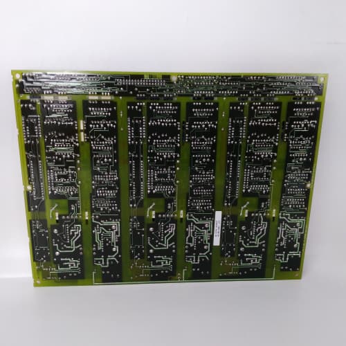
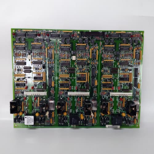
Synchronous motors need controlled field excitation—too little and they lose synchronism, too much and they overheat. The 531X190SRCAFG1 provides that control, regulating the field current based on load and power factor.
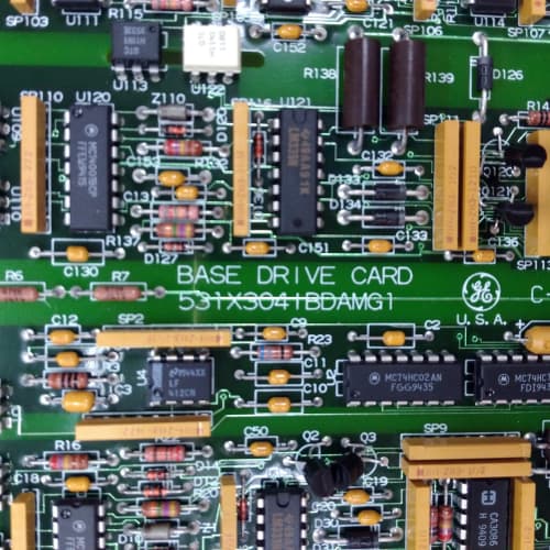
The AFG1 is the synchronous motor control board for the 1900 platform. It replaced the AEG1, which had 4 CT and 2 VT inputs. GE added 2 more CT and 2 more VT inputs, and upgraded the field current output to 4–20 mA. I’ve used the AFG1 on a 5,000 HP synchronous compressor—the board regulated the field current to maintain the motor’s power factor at 0.95, saving energy.
Key Technical Specifications
| Parameter | Specification |
|---|---|
| Manufacturer | General Electric |
| Product Series | 1900 Drive Platform |
| Board Type | Synchronous Motor Control / Excitation Control |
| CT Inputs | 6 channels, 0–5 A AC, 50/60 Hz, 0.2% accuracy |
| VT Inputs | 4 channels, 0–600 V AC, 50/60 Hz, 0.2% accuracy |
| Field Current Output | 2 channels, 4–20 mA, 12-bit resolution, 500 Ω max load |
| Digital Inputs | 4 channels, 24 V DC, optically isolated |
| Digital Outputs | 4 channels, MOSFET, 0.5 A, 24 V DC |
| Power Factor Control | 0.80–1.00 (programmable) |
| Protection | Field loss, overexcitation, underexcitation, out-of-step |
| Isolation | 2,500 V RMS (field to logic) |
| Status LEDs | D1 (power), D2 (excitation active), D3 (power factor), D4 (fault) |
| Supply Voltage | 5 V DC (logic) and 24 V DC (field) |
| Current Draw | 0.9 A @ 5 V, 0.5 A @ 24 V |
| Operating Temperature | 0 to +55 °C |
| Storage Temperature | −40 to +85 °C |
| Connectors | 6 CT terminal blocks (J1–J6); 4 VT terminal blocks (J7–J10); two 10-pin terminal blocks (J11–J12, field current); 10-pin header (J13, digital I/O); 34-pin ribbon (J14, logic interface) |
| Mounting | 4 × M3 screws, standard 1900 drive rack |
Quality Inspection Process (SOP Transparency)
Incoming Verification
We match the OEM packing slip against GE’s production records—AFG1 boards were produced from 2011 through 2015. Anti-counterfeit check: authentic boards have a precision ADC (Analog Devices AD7091) with the ADI logo. Visual inspection: we check the CT and VT terminal blocks for bent pins. Accessories: we inventory the 6 CT terminal plugs and the calibration plug.
Live Functional Test
Test rack: a GE 1900 drive simulator with a 5 A AC current source, a 600 V AC voltage source, a field current simulator (4–20 mA load), and a Keysight 34465A multimeter. Power-up: 5 V and 24 V supplies from a Lambda GEN-60. LED D1 (green) comes on; D2 flashes during excitation; D3 reflects power factor; D4 stays off.
CT test: we inject 0, 1, 2, 3, 4, and 5 A AC—the reading must be within 0.2%. VT test: we inject 0, 100, 200, 300, 400, 500, and 600 V AC—the reading must be within 0.2%. Field current test: we command 4, 8, 12, 16, and 20 mA—must be within 0.5%. Power factor test: we vary the load and verify the board adjusts the field current to maintain the programmed power factor. Protection test: we simulate a field loss—the board must trip the output within 100 ms. Isolation test: we apply 2,500 V for 1 minute—no breakdown.
Electrical Parameters
Insulation resistance: 500 V megger—>20 MΩ. Ground continuity: <0.1 Ω.
Firmware Verification
We read the firmware version—the AFG1 runs firmware v2.05 or later.
Final QC & Packaging
QC engineer signs off. Calibration certificate included. Anti-static bag with desiccant. Two layers of ESD foam, then a carton. “QC Passed” label with test date, firmware version, and inspector ID.
Field Replacement Pitfalls
1. CT Polarity—Match the Phase
The CT inputs are polarized. If you reverse the polarity, the power factor calculation is wrong. ❗ Match the CT polarity to the phase.
2. VT Phase Connection—Match the CT
The VT inputs must be connected to the same phases as the CTs.
3. Field Current Output—4–20 mA Only
The field current output is 4–20 mA only—no 0–10 V option. If the exciter expects a voltage signal, add an external converter.
4. Power Factor Setpoint—Set Correctly
The power factor setpoint must match the motor’s design. We saw a site with a 0.85 setpoint on a 0.95 motor—the motor overheated.
5. Protection Settings—Don’t Disable
The AFG1 has field loss, overexcitation, underexcitation, and out-of-step protection. Don’t disable these—they protect the motor.
New Original vs. Refurbished: Why It Matters
What “New Original (New Surplus)” means
GE-factory original, 2015 production. The ADC is factory-tested. The field current outputs have zero hours.
Refurbished risk in plain terms
The CT inputs might have drift—we measured a refurbished board with a 0.5% CT error. The field current output might have drift—we measured a refurbished board with a 0.3 mA offset.
Real cost of a refurbished failure
A synchronous motor loses synchronism because the field current is wrong—the motor trips. Cost: 40,000. The refurbished AFG1 cost 1,400; the new surplus board costs 1,700. Pay the 300.
What we provide as proof
Original GE box label photo. CT/VT accuracy verified. Field current calibrated. Power factor control tested. Anti-static bag sealed.
Performance Benchmarks & Test Results
All tests run on a GE 1900 drive simulator, ambient 25 °C ±1 °C, 5.00 V DC logic supply, firmware v2.05.
| Test Condition | Measured Result | Notes |
|---|---|---|
| CT accuracy (5 A) | ±0.15% | |
| VT accuracy (600 V) | ±0.15% | |
| Field current accuracy (20 mA) | ±0.3% | |
| Power factor accuracy | ±0.01 PF | |
| Field loss trip time | 85 ms | |
| 5 V current draw | 0.88 A at 5.00 V | |
| MTBF | 38,000 hours | Derates to 19,000 hours at 55 °C |
Field reality: The AFG1 is a synchronous motor control board—6 CT, 4 VT, field current output (4–20 mA), power factor control, and 2,500 V isolation. We’ve used it on 5,000 HP synchronous compressors and large synchronous motors. The power factor control is the key—it improves motor efficiency and reduces energy costs. The AFG1 is a reliable synchronous motor control board for large synchronous motor applications.
A-B 1756-RM/A
HONEYWELL FC-SAI-1620M V1.4
A-B 1769-L32C
 Email: sales@plcfcs.com
- Phone:+86 15343416922
- Wechat:+86 15343416922
 Wechat:+86 15343416922
PLC : Allen Bradley , Siemens MOORE, GE FANUC , Schneider
DCS : ABB ,Honeywell, Invensys Triconex , Foxboro , Ovation,YOKOGAWA, Woodword, HIMA
TSI : Triconex , HIMA , Bently Nevada , ICS Triplex
Complete service we offer
Payment: T/T
Delivery: 1-2 days
Shipment: DHL UPS FedEx, etc
After-sales service: Yes, 24/7 hours