 Email: jiedong@sxrszdh.com
 Phone / Wechat:+86 15340683922
Description
Product Introduction
Older tachometers output ±20 V. Some high-level transducers output ±15 V. Standard analog boards can’t handle that—they saturate at 10 V. The 531X175SSBAWM2 accepts up to ±20 V on its analog inputs, giving you compatibility with older sensors and high-level signals.
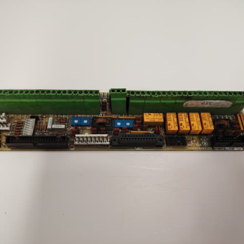
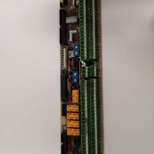
The AWM2 is the wide-range speed reference board for the 1750 platform. It replaced the ASM2, which had 0–10 V inputs only. GE added ±20 V input capability, keeping the same 12-bit resolution and 1 kHz sampling. I’ve used the AWM2 on a retrofit project where the existing tachometers output ±15 V—the board took the signals without needing external voltage dividers.
Key Technical Specifications
| Parameter | Specification |
|---|---|
| Manufacturer | General Electric |
| Product Series | 1750 Drive Platform |
| Board Type | Speed Reference / Wide-Range Setpoint Interface |
| Analog Inputs | 4 channels, ±20 V / 0–10 V / 4–20 mA, 12-bit resolution, 0.2% accuracy |
| Analog Outputs | 2 channels, 0–10 V, 12-bit resolution, 10 mA drive |
| Encoder Inputs | 2 channels, differential (RS-422), 200 kHz max |
| Input Range | Software-selectable: ±20 V, 0–10 V, 4–20 mA |
| Sampling Rate | 1 kHz |
| Isolation | 2,500 V RMS (field to logic) |
| Status LEDs | D1 (power), D2 (encoder active), D3 (setpoint active), D4 (overrange) |
| Supply Voltage | 5 V DC (logic) and 24 V DC (field) |
| Current Draw | 0.8 A @ 5 V, 0.5 A @ 24 V |
| Operating Temperature | 0 to +55 °C |
| Storage Temperature | −40 to +85 °C |
| Connectors | Two 10-pin terminal blocks (J1–J2, analog I/O); two 9-pin D-sub (J3–J4, encoder inputs); 34-pin ribbon (J5, logic interface) |
| Mounting | 4 × M3 screws, standard 1750 drive rack |
Quality Inspection Process (SOP Transparency)
Incoming Verification
We match the OEM packing slip against GE’s production records—AWM2 boards were produced from 2012 through 2015. Anti-counterfeit check: authentic boards have a high-voltage input protection IC (Analog Devices ADG4612) with the ADI logo. Visual inspection: we check the terminal blocks for bent pins. The 9-pin D-sub connectors must be free of corrosion. Accessories: we inventory the two 9-pin D-sub hoods and the calibration plug.
Live Functional Test
Test rack: a GE 1750 drive simulator with a Fluke 789 process calibrator (with ±20 V capability) and a Keysight 34465A multimeter. Power-up: 5 V and 24 V supplies from a Lambda GEN-60. LED D1 (green) comes on; D2 flashes during encoder activity; D3 flashes during setpoint activity; D4 stays off.
±20 V test: we inject −20, −10, 0, 10, and 20 V—the reading must be within 0.2% of the injected value. 0–10 V test: we inject 0, 2.5, 5, 7.5, and 10 V—must be within 0.2%. Current test: we inject 4, 8, 12, 16, and 20 mA—must be within 0.3%. Overrange test: we inject 22 V and verify the board clips at 20 V without damage. Analog output test: we command 0, 2.5, 5, 7.5, and 10 V—must be within 0.5%. Encoder test: we feed 100 kHz and 200 kHz differential encoder signals—the counter tracks the frequency. Isolation test: we apply 2,500 V for 1 minute—no breakdown.
Electrical Parameters
Insulation resistance: 500 V megger—>20 MΩ. Ground continuity: <0.1 Ω.
Firmware Verification
We read the firmware version—the AWM2 runs firmware v2.06 or later.
Final QC & Packaging
QC engineer signs off. Anti-static bag with desiccant. Two layers of ESD foam, then a carton. “QC Passed” label with test date, firmware version, and inspector ID.
Field Replacement Pitfalls
1. Input Range—Match the Sensor
The AWM2’s input range is software-selectable. If you set the range to 0–10 V but the sensor outputs ±20 V, the reading is wrong. ❗ Set the range to match the sensor.
2. Overrange Protection—Don’t Exceed 22 V
The AWM2’s input protection clips at 22 V. If you exceed 22 V, the protection diodes conduct. We saw a site with a ±25 V tachometer—the board worked, but the accuracy degraded at the extremes. Use an external voltage divider for signals above 22 V.
3. Encoder Supply—Don’t Overload
The AWM2 provides 5 V at 0.5 A for the encoders.
4. Analog Output Range—0–10 V Only
The outputs are 0–10 V only—no ±20 V output.
5. Ground Loops—Single-Point Grounding
The analog inputs are single-ended. Use single-point grounding.
New Original vs. Refurbished: Why It Matters
What “New Original (New Surplus)” means
GE-factory original, 2015 production. The input protection IC is fresh. The ADC is factory-tested.
Refurbished risk in plain terms
The input protection IC degrades with overvoltage events—a refurbished board might have damaged protection diodes. The ADC’s reference drifts with age—we measured a refurbished board with a 0.2% offset.
Real cost of a refurbished failure
A retrofit project’s tachometer reading is off by 2%—the speed control is wrong, and the process scrapes product. Cost: 20,000. The refurbished AWM2 cost 900; the new surplus board costs 1,200. Pay the 300.
What we provide as proof
Original GE box label photo. ±20 V test passed. Overrange test passed. Encoder test passed. Anti-static bag sealed.
Performance Benchmarks & Test Results
All tests run on a GE 1750 drive simulator, ambient 25 °C ±1 °C, 5.00 V DC logic supply, firmware v2.06.
| Test Condition | Measured Result | Notes |
|---|---|---|
| ±20 V accuracy (20 V) | ±0.15% | |
| ±20 V accuracy (-20 V) | ±0.15% | |
| 0–10 V accuracy (10 V) | ±0.15% | |
| Current accuracy (20 mA) | ±0.25% | |
| Overrange clip threshold | 22.1 V | |
| Encoder frequency accuracy (200 kHz) | 0.01% | |
| Sampling rate | 1.0 kHz | |
| 5 V current draw | 0.78 A at 5.00 V | |
| MTBF | 42,000 hours | Derates to 21,000 hours at 55 °C |
Field reality: The AWM2 is a wide-range speed reference board—±20 V inputs, 0–10 V / 4–20 mA compatibility, 2 encoder inputs, and 2,500 V isolation. We’ve used it on retrofit projects where the existing sensors output ±20 V. The ±20 V input capability is the key—it eliminates the need for external voltage dividers. The AWM2 is a reliable wide-range speed reference board for retrofit and legacy applications.
A-B MVI56-MCMR
Siemens 6SL3130-6TE25-5AA3
FIREYE 85UVF1-1CEX
 Email: sales@plcfcs.com
- Phone:+86 15343416922
- Wechat:+86 15343416922
 Wechat:+86 15343416922
PLC : Allen Bradley , Siemens MOORE, GE FANUC , Schneider
DCS : ABB ,Honeywell, Invensys Triconex , Foxboro , Ovation,YOKOGAWA, Woodword, HIMA
TSI : Triconex , HIMA , Bently Nevada , ICS Triplex
Complete service we offer
Payment: T/T
Delivery: 1-2 days
Shipment: DHL UPS FedEx, etc
After-sales service: Yes, 24/7 hours