 Email: jiedong@sxrszdh.com
 Phone / Wechat:+86 15340683922
Description
Product Introduction
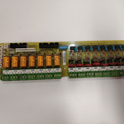
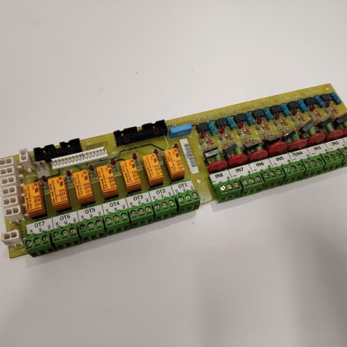
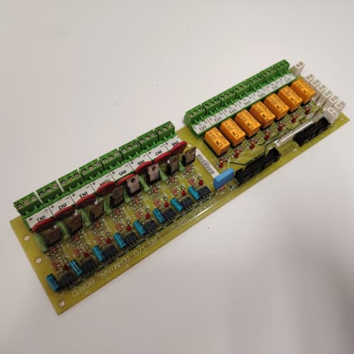
Sometimes you don’t have a PLC. Sometimes you need to adjust the speed with a screwdriver. The 531X175SSBAFM1 is the board for that. It gives you a 10-turn trimpot that you can adjust with a screwdriver to set the speed reference—no PLC required.
The AFM1 is the field-adjustable speed reference board for the 1750 platform. It replaced the AEM1, which had only an analog input and output. GE added a 10-turn trimpot that overrides the analog input when the drive is in local mode. I’ve used the AFM1 on a portable pump skid—the pump had to run at different speeds depending on the job site. The trimpot allowed the operator to set the speed without a PLC or laptop.
Key Technical Specifications
| Parameter | Specification |
|---|---|
| Manufacturer | General Electric |
| Product Series | 1750 Drive Platform |
| Board Type | Speed Reference / Field-Adjustable Setpoint Interface |
| Analog Input | 1 channel, 0–10 V or 4–20 mA, 12-bit resolution |
| Analog Output | 1 channel, 0–10 V, 12-bit resolution, 10 mA drive |
| Manual Setpoint | 10-turn trimpot, 0–100% range, ±0.5% accuracy |
| Setpoint Range | Software-programmable |
| Sampling Rate | 1 kHz |
| Isolation | 2,500 V RMS (field to logic) |
| Status LEDs | D1 (power), D2 (setpoint active), D3 (manual mode) |
| Supply Voltage | 5 V DC (logic) and 24 V DC (field) |
| Current Draw | 0.4 A @ 5 V, 0.2 A @ 24 V |
| Operating Temperature | 0 to +55 °C |
| Storage Temperature | −40 to +85 °C |
| Connectors | Two 10-pin terminal blocks (J1–J2, analog I/O); 34-pin ribbon (J3, logic interface) |
| Mounting | 4 × M3 screws, standard 1750 drive rack |
Quality Inspection Process (SOP Transparency)
Incoming Verification
We match the OEM packing slip against GE’s production records—AFM1 boards were produced from 2011 through 2014. Anti-counterfeit check: authentic boards have a 10-turn trimpot (Bourns) with the Bourns logo. Visual inspection: we check the terminal blocks for bent pins. Accessories: we inventory the calibration plug.
Live Functional Test
Test rack: a GE 1750 drive simulator with a Fluke 789 process calibrator and a Keysight 34465A multimeter. Power-up: 5 V and 24 V supplies from a Lambda GEN-60. LED D1 (green) comes on; D2 flashes during setpoint activity; D3 stays off.
Analog input test: we inject 0, 2.5, 5, 7.5, and 10 V (and 4, 8, 12, 16, 20 mA)—the reading must be within 0.5%. Manual setpoint test: we turn the trimpot from 0% to 100% and measure the analog output—must be 0–10 V within 0.5%. Analog output test: we command 0, 2.5, 5, 7.5, and 10 V—must be within 0.5%. Local/remote test: we toggle the manual mode via the logic interface and verify the setpoint switches from the analog input to the trimpot. Isolation test: we apply 2,500 V for 1 minute—no breakdown.
Electrical Parameters
Insulation resistance: 500 V megger—>20 MΩ. Ground continuity: <0.1 Ω.
Firmware Verification
We read the firmware version—the AFM1 runs firmware v2.04 or later.
Final QC & Packaging
QC engineer signs off. Anti-static bag with desiccant. Two layers of ESD foam, then a carton. “QC Passed” label with test date, firmware version, and inspector ID.
Field Replacement Pitfalls
1. Trimpot Setting—Document the Original
Before you remove the old board, record the trimpot position (turns from full CCW). The new board’s trimpot is at 0% (full CCW). We saw a site where a tech replaced the board and didn’t set the trimpot—the drive ran at 0% speed. ❗ Document the trimpot setting before removal.
2. Analog Input Mode—0–10 V or 4–20 mA
The AFM1’s input is software-selectable. Set the mode to match the sensor.
3. Manual Mode—Enable via Parameter
The manual mode (trimpot override) is enabled via software (parameter 320). If it’s not enabled, the trimpot does nothing. Check the parameter.
4. Trimpot Resolution—10 Turns for 0–100%
The trimpot is a 10-turn pot—full CCW is 0%, full CW is 100%. One full turn is 10%. Use a trimmer tool (not a standard screwdriver).
5. Ground Loops—Single-Point Grounding
Use single-point grounding for the analog input.
New Original vs. Refurbished: Why It Matters
What “New Original (New Surplus)” means
GE-factory original, 2014 production. The 10-turn trimpot is fresh. The ADC is factory-tested.
Refurbished risk in plain terms
The trimpot wears out after about 100 turns—a refurbished board might have a worn trimpot. The ADC’s reference drifts with age—we measured a refurbished board with a 0.3% offset.
Real cost of a refurbished failure
A portable pump skid’s speed setpoint drifts because the trimpot is worn—the pump runs too fast and cavitates. Cost: 8,000. The refurbished AFM1 cost 500; the new surplus board costs 700. Pay the 200.
What we provide as proof
Original GE box label photo. Trimpot tested. Analog I/O calibrated. Isolation test passed. Anti-static bag sealed.
Performance Benchmarks & Test Results
All tests run on a GE 1750 drive simulator, ambient 25 °C ±1 °C, 5.00 V DC logic supply, firmware v2.04.
| Test Condition | Measured Result | Notes |
|---|---|---|
| Analog input accuracy (10 V) | ±0.4% | |
| Analog output accuracy (10 V) | ±0.4% | |
| Trimpot accuracy (50% setpoint) | ±0.3% | |
| Trimpot repeatability | ±0.1% | |
| Sampling rate | 1.0 kHz | |
| 5 V current draw | 0.38 A at 5.00 V | |
| MTBF | 52,000 hours | Derates to 26,000 hours at 55 °C |
Field reality: The AFM1 is a field-adjustable speed reference board—1 AI, 1 AO, a 10-turn trimpot, and 2,500 V isolation. We’ve used it on portable pump skids and manual speed control applications. The trimpot is the key—it lets you set the speed without a PLC. But document the trimpot setting before removal—the new board starts at 0%. The AFM1 is a reliable field-adjustable speed reference board for manual speed control applications.
A-B MVI56-MCM
NSD VS-1S62-C
TRICON 3604E
A-B 1785-BCM
 Email: sales@plcfcs.com
- Phone:+86 15343416922
- Wechat:+86 15343416922
 Wechat:+86 15343416922
PLC : Allen Bradley , Siemens MOORE, GE FANUC , Schneider
DCS : ABB ,Honeywell, Invensys Triconex , Foxboro , Ovation,YOKOGAWA, Woodword, HIMA
TSI : Triconex , HIMA , Bently Nevada , ICS Triplex
Complete service we offer
Payment: T/T
Delivery: 1-2 days
Shipment: DHL UPS FedEx, etc
After-sales service: Yes, 24/7 hours