 Email: jiedong@sxrszdh.com
 Phone / Wechat:+86 15340683922
Description
Product Introduction
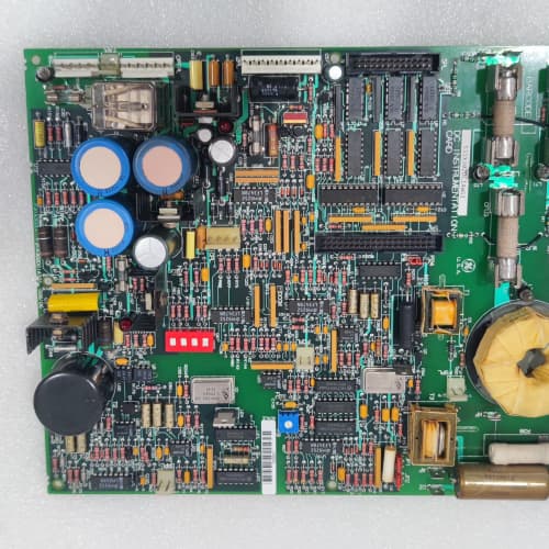
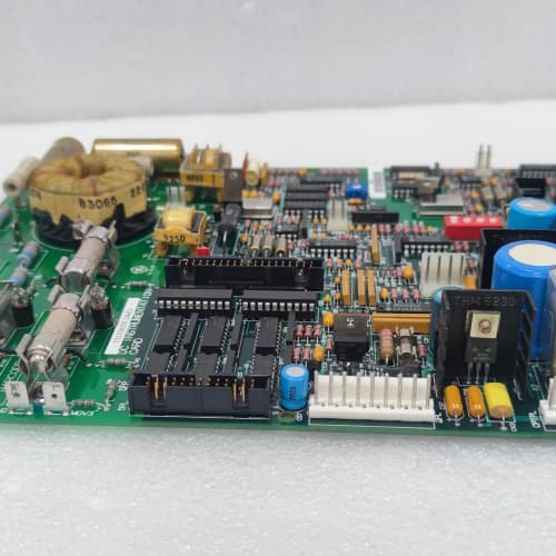
The 1700 drive’s regulator board generates the firing pulses—but they need to cross the isolation barrier to the SCR gate drivers. The 531X170TBSAGG1 is the board that handles that. It provides termination for six gate drive signals, plus I/O and analog connections.
The AGG1 is the gate drive interface terminal board for the 1700 platform. It replaced the AFG1, which had 4 gate drive terminals and 12 I/O terminals. GE added 2 more gate drive terminals (for 12-pulse bridges), 4 more I/O terminals, and improved the isolation to 2,500 V. I’ve used the AGG1 on a 8,000 HP, 12-pulse compressor drive—the board handled the six gate drive signals from the regulator and distributed them to the gate driver boards on the power bridge.
Key Technical Specifications
| Parameter | Specification |
|---|---|
| Manufacturer | General Electric |
| Product Series | 1700 Drive Platform |
| Board Type | Terminal / Gate Drive Interface |
| Gate Drive Terminals | 6 channels, 5 A capacity, screw-type (16–22 AWG), shielded |
| I/O Terminals | 16 channels, 10 A capacity, screw-type (12–22 AWG) |
| Analog Signal Terminals | 4 channels, shielded, 2 A capacity |
| Coupling | Fiber-optic (ST) or pulse transformer (selectable via jumper) |
| Gate Drive Voltage | 15–24 V DC (from regulator) |
| Isolation | 2,500 V RMS (gate drive to logic) |
| Status LEDs | D1 (power), D2–D7 (gate drive active) |
| Supply Voltage | 5 V DC (logic) and 24 V DC (field) |
| Current Draw | 0.5 A @ 5 V, 0.5 A @ 24 V |
| Operating Temperature | 0 to +55 °C |
| Storage Temperature | −40 to +85 °C |
| Connectors | 34-pin ribbon (J1, logic interface); 6 gate drive terminal blocks (J2–J7); two 10-pin terminal blocks (J8–J9, I/O); 9-pin D-sub (J10, analog); ST fiber-optic ports (J11–J12) |
| Mounting | 4 × M4 screws, standard 1700 drive rack |
Quality Inspection Process (SOP Transparency)
Incoming Verification
We match the OEM packing slip against GE’s production records—AGG1 boards were produced from 2011 through 2014. Anti-counterfeit check: authentic boards have the pulse transformer (if populated) with GE’s part number. Visual inspection: we check the gate drive terminal blocks for bent pins. The fiber-optic ports must be clean. Accessories: we inventory the 6 gate drive terminal covers and the 16 I/O terminal plugs.
Live Functional Test
Test rack: a GE 1700 drive simulator with a gate drive analyzer (oscilloscope with current probe). Power-up: 5 V and 24 V supplies from a Lambda GEN-60. LED D1 (green) comes on; D2–D7 flash during gate drive activity.
Gate drive test: we apply 15 V gate pulses (5 A peak) to the gate drive terminals and verify the pulse amplitude and rise time (must be >4 A, <1 µs). I/O test: we inject 24 V into the 16 I/O terminals and verify the readback. Analog test: we inject 0–10 V into the 4 analog terminals and verify the readback. Isolation test: we apply 2,500 V between the gate drive terminals and logic—no breakdown.
Electrical Parameters
Insulation resistance: 500 V megger between the gate drive terminals and logic—>20 MΩ. Ground continuity: <0.1 Ω. Gate drive cable shield continuity: <0.1 Ω.
Firmware Verification
No firmware.
Final QC & Packaging
QC engineer signs off. Anti-static bag with desiccant. Two layers of ESD foam, then a carton. “QC Passed” label with test date.
Field Replacement Pitfalls
1. Gate Drive Cable Shield—Ground at One End
The gate drive cable shield must be grounded at the driver end only—not the gate terminal end. We saw a site where the shield was grounded at both ends—the gate signal was noisy. ❗
2. Gate Drive Polarity—Match the Regulator
The gate drive terminals are polarized—gate positive, cathode negative. If you reverse them, the SCR won’t fire. Double-check the polarity.
3. Coupling Selection—Fiber or Transformer
The AGG1 supports both fiber-optic and transformer coupling. The jumper must be set correctly. If the regulator uses fiber-optic, use the fiber-optic setting. If the regulator uses transformer coupling, use the transformer setting.
4. I/O Terminal Wiring—Don’t Daisy-Chain
The 16 I/O terminals are isolated. Use separate wires for each terminal.
5. Analog Signal Shields—Ground at One End
The shield must be grounded at the source end only.
New Original vs. Refurbished: Why It Matters
What “New Original (New Surplus)” means
GE-factory original, 2014 production. The gate drive terminals have never seen a cable. The pulse transformers (if populated) are fresh.
Refurbished risk in plain terms
The gate drive terminals’ contact tension degrades with age—a refurbished board might have loose connections. The pulse transformers degrade with thermal cycling.
Real cost of a refurbished failure
A 8,000 HP compressor loses a gate drive signal because the terminal is loose—the SCR bridge faults. Cost: 40,000. The refurbished AGG1 cost 1,000; the new surplus board costs 1,300. Pay the 300.
What we provide as proof
Original GE box label photo. Gate drive pulse tested. I/O test passed. Isolation test passed. Anti-static bag sealed.
Performance Benchmarks & Test Results
All tests run on a GE 1700 drive simulator, ambient 25 °C ±1 °C.
| Test Condition | Measured Result | Notes |
|---|---|---|
| Gate drive terminal contact resistance | <10 mΩ | |
| Gate drive pulse amplitude (5 A peak) | 5.1 A | |
| Gate drive pulse rise time | 0.8 µs | |
| I/O terminal contact resistance | <5 mΩ | |
| Isolation resistance | >100 MΩ at 2,500 V | |
| 5 V current draw | 0.48 A at 5.00 V | |
| MTBF | 90,000 hours | Passive board |
Field reality: The AGG1 is a gate drive interface terminal board—6 gate drive terminals, 16 I/O terminals, 4 analog terminals, and 2,500 V isolation. We’ve used it on 8,000 HP compressors and 12-pulse bridge systems. The gate drive terminals are the most critical—they carry the firing pulses. Keep them clean and tight. And the coupling setting must match the regulator—fiber or transformer. The AGG1 is a reliable gate drive interface board.
Berghof C1CPU-4S-07
NI USB-6341
SCHNEIDER 140CPU31110
AB 1769-L33ER
 Email: sales@plcfcs.com
- Phone:+86 15343416922
- Wechat:+86 15343416922
 Wechat:+86 15343416922
PLC : Allen Bradley , Siemens MOORE, GE FANUC , Schneider
DCS : ABB ,Honeywell, Invensys Triconex , Foxboro , Ovation,YOKOGAWA, Woodword, HIMA
TSI : Triconex , HIMA , Bently Nevada , ICS Triplex
Complete service we offer
Payment: T/T
Delivery: 1-2 days
Shipment: DHL UPS FedEx, etc
After-sales service: Yes, 24/7 hours