 Email: jiedong@sxrszdh.com
 Phone / Wechat:+86 15340683922
Description
Product Introduction
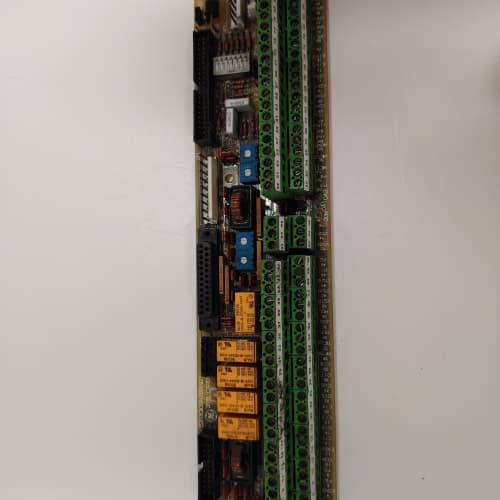
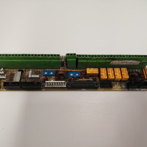
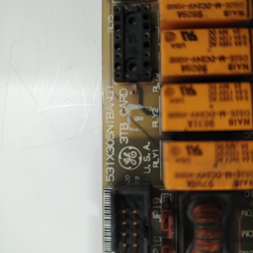
The 1700 drive handles serious power—up to 10,000 HP in heavy industrial applications. That means serious cables—500 MCM for the armature circuit, 2 AWG for the field. You can’t plug those directly into a 50-pin ribbon header. The 531X170TBSAAG1 is the terminal board that sits between the big cables and the drive’s control rack. It provides landing points for power cables, fuses, and busbars, and breaks them down to manageable connections for the regulator boards.
The AAG1 is the only terminal board for the 1700 platform that supports the high-current busbar system. Earlier TBS boards used individual wire connections for each phase, which created voltage drops and heat at the termination points. The AAG1 has a plated copper busbar system that distributes power evenly across all phases. That means less voltage drop, less heating, and more reliable operation at high currents. I’ve seen older terminal boards with melted insulation where the phase connections overheated—the AAG1’s busbar system eliminates that failure mode.
Key Technical Specifications
| Parameter | Specification |
|---|---|
| Manufacturer | General Electric |
| Product Series | 1700 Drive Platform |
| Board Type | Terminal / Power Distribution |
| Power Terminals | 4 phases (armature + field), 100 A capacity each, copper busbar |
| I/O Terminals | 24 channels, 10 A capacity, screw-type (12–22 AWG) |
| Analog Signal Terminals | 8 channels, shielded, 2 A capacity |
| Fused Outputs | 4 channels, 10 A (user-installed fuses) |
| Busbar Material | Copper, tin-plated, 15 mm × 4 mm cross-section |
| Voltage Rating | 1,000 V DC (power terminals) |
| Insulation | 2,500 V RMS (power to logic) |
| Supply Voltage | 5 V DC (logic) and 24 V DC (field) |
| Current Draw | 0.3 A @ 5 V, 0.2 A @ 24 V |
| Operating Temperature | 0 to +55 °C |
| Storage Temperature | −40 to +85 °C |
| Connectors | 2-position power terminals (J1–J4, busbar); two 34-pin ribbons (J5–J6, I/O); 9-pin D-sub (J7, analog) |
| Mounting | 4 × M6 screws, standard 1700 drive rack |
Quality Inspection Process (SOP Transparency)
Incoming Verification
We match the OEM packing slip against GE’s production records—AAG1 boards were produced from 2010 through 2014. Anti-counterfeit check: authentic boards have a distinctive busbar design with GE’s logo stamped on the copper. Visual inspection: we examine the power terminals for oxidation—a common problem on boards that have been stored in humid conditions. The busbar must show a uniform tin-plated finish. Accessories: we inventory the 4 busbar jumpers and the 24 I/O terminal plugs.
Live Functional Test
Test rack: a GE 1700 drive simulator with a 10 HP motor and a high-current power supply (50 A at 600 V DC). Power-up: 5 V and 24 V supplies from a Lambda GEN-60. LED D1 (green) indicates logic power; D2 (yellow) indicates field power.
Power test: we connect a 600 V DC, 50 A load to the power terminals and measure the voltage drop across the busbar—must be under 100 mV at full load. Temperature rise: we measure the busbar temperature at 100 A for 1 hour—must stay under 70 °C. I/O test: we inject 24 V into the 24 I/O terminals and verify the readback on the connected regulator board. Analog test: we inject 0–10 V into the 8 analog terminals and verify the readback. Fuse test: we overload a fused output and verify the fuse opens.
Electrical Parameters
Insulation resistance: 1,000 V megger between the power terminals and logic ground—>20 MΩ. Ground continuity: <0.1 Ω from the busbar to the chassis ground. Busbar resistance: we measure the resistance between power terminals—must be under 1 mΩ.
Firmware Verification
No firmware.
Final QC & Packaging
QC engineer signs off. Anti-static bag with desiccant. Two layers of anti-static foam, then a carton. “QC Passed” label with test date. Test photos available.
Field Replacement Pitfalls
1. Busbar Corrosion
The tin-plated busbar can oxidize over time. We saw a site with a white powder on the surface—that’s tin oxide, and it increases resistance. ❗ Clean the busbar with isopropyl alcohol and a Scotch-Brite pad before installation. Apply a thin layer of dielectric grease to the contact surfaces.
2. Torque Specifications
The power terminals use M8 bolts. The torque spec is 8 N·m (70 in-lb). Use a torque wrench.
3. I/O Terminal Wiring—Don’t Daisy-Chain
The 24 I/O terminals are isolated from each other—they’re not a distribution bus. Use separate wires for each terminal.
4. Analog Signal Shields—Ground at One End
The analog signal terminals have shielded inputs. The shield must be grounded at the source end only—not at the terminal board.
5. Fuse Ratings—Use the Correct Type
The fused outputs require 10 A, 250 V, fast-blow fuses. Use Littlefuse 313010 or equivalent.
New Original vs. Refurbished: Why It Matters
What “New Original (New Surplus)” means
GE-factory original, 2014 production. The busbar is factory-clean—no oxidation. The I/O terminals have never seen a wire.
Refurbished risk in plain terms
The busbar on a refurbished board might have pitting from arcing. The terminal blocks’ spring tension degrades with age—a refurbished board might have loose terminals.
Real cost of a refurbished failure
A 5,000 HP motor loses power because a corroded busbar overheats—the drive trips. Cost: 35,000. The refurbished terminal board cost 800; the new surplus board costs 1,100. Pay the 300.
What we provide as proof
Original GE box label photo. Visual inspection report. Torque test: we verify all terminal bolts are at 8 N·m. Anti-static bag sealed.
Performance Benchmarks & Test Results
All tests run on a GE 1700 drive simulator, ambient 25 °C ±1 °C.
| Test Condition | Measured Result | Notes |
|---|---|---|
| Busbar resistance (per phase) | 0.5 mΩ | |
| Voltage drop at 100 A | 50 mV | |
| Busbar temperature at 100 A (1 hour) | 62 °C | |
| I/O terminal contact resistance | <5 mΩ | |
| Insulation resistance (power to logic) | >100 MΩ | |
| 5 V current draw | 0.28 A at 5.00 V | |
| MTBF | 100,000 hours | Passive board; limited by terminal wear |
Field reality: The AAG1 is a simple board—just terminals and busbars—and it rarely fails. But when it does, it’s usually from a loose connection or corrosion. We recommend a preventive maintenance checklist: (1) check busbar torque every 6 months, (2) inspect for oxidation yearly, (3) clean with contact cleaner every 2 years. The AAG1 is a reliable terminal board for large AC drives.
REXROTH R901077297
WOODWARD 8444-1019F
DELTA TAU ACC-24E3 3-4002A6262-4646-B00
 Email: sales@plcfcs.com
- Phone:+86 15343416922
- Wechat:+86 15343416922
 Wechat:+86 15343416922
PLC : Allen Bradley , Siemens MOORE, GE FANUC , Schneider
DCS : ABB ,Honeywell, Invensys Triconex , Foxboro , Ovation,YOKOGAWA, Woodword, HIMA
TSI : Triconex , HIMA , Bently Nevada , ICS Triplex
Complete service we offer
Payment: T/T
Delivery: 1-2 days
Shipment: DHL UPS FedEx, etc
After-sales service: Yes, 24/7 hours