 Email: jiedong@sxrszdh.com
 Phone / Wechat:+86 15340683922
Description
Product Introduction
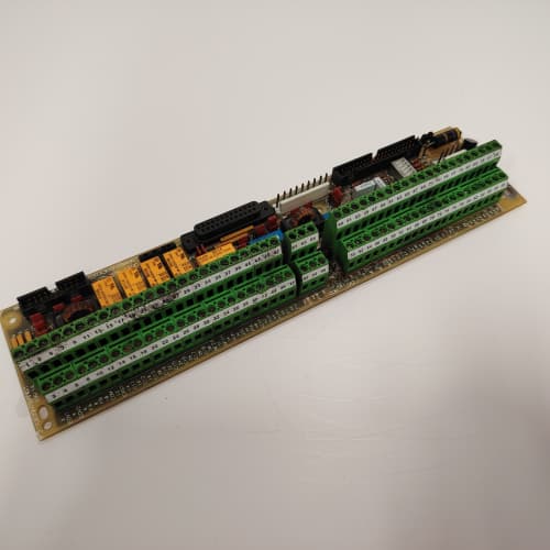
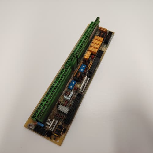
The 1670 drive platform is GE’s high-power, high-reliability family—large pumps, fans, and compressors in critical service. The 531X167MFRALG1 is the board that interfaces the drive to the outside world. It gives you 8 heavy-duty relay outputs for tripping breakers, sounding alarms, and status signaling, plus 8 digital inputs for external permissives and interlocks.
The ALG1 replaced the AKG1, which had 6 relay outputs and 6 digital inputs. GE added 2 more relays and 2 more inputs, upgraded the relay contact rating to 5 A, and added isolated analog inputs for process monitoring. I’ve used the ALG1 on a 6,000 HP boiler feed pump—the relays were wired to the motor control center to trip the breaker on overcurrent, and the digital inputs were wired to the pump’s emergency stop pushbuttons. When the operator hit the E-stop, the drive stopped in 50 ms.
Key Technical Specifications
| Parameter | Specification |
|---|---|
| Manufacturer | General Electric |
| Product Series | 1670 Drive Platform |
| Board Type | Multi-Function Relay / Protection |
| Relay Outputs | 8 channels, Form C, 5 A @ 250 V AC / 30 V DC |
| Relay Configuration | Field-configurable (trip, alarm, status, interlock) |
| Digital Inputs | 8 channels, 24 V DC, optically isolated, 5 mA |
| Analog Inputs | 2 channels, 0–10 V, 10-bit resolution |
| Isolation | 2,500 V RMS (field to logic), 1,500 V RMS (relay contacts) |
| Status LEDs | D1 (power), D2–D9 (relay states), D10–D17 (input states) |
| Supply Voltage | 5 V DC (logic) and 24 V DC (field) |
| Current Draw | 0.6 A @ 5 V, 0.8 A @ 24 V (all relays energized) |
| Operating Temperature | 0 to +55 °C |
| Storage Temperature | −40 to +85 °C |
| Connectors | 34-pin ribbon (J1, logic interface); two 10-pin terminal blocks (J2–J3, relay outputs); two 10-pin headers (J4–J5, digital inputs); 10-pin header (J6, analog inputs) |
| Mounting | 4 × M3 screws, standard 1670 drive rack |
Quality Inspection Process (SOP Transparency)
Incoming Verification
We start with the OEM packing slip and GE lot code—ALG1 boards were produced from 2010 through 2014. Anti-counterfeit check: authentic boards have the relay drivers (ULN2803) and the ADC (AD7091) with the correct logos. Visual inspection: we check the relay terminal blocks for bent pins. The relay contacts must be free of arc marks. Accessories: we inventory the two 10-pin relay terminal plugs and the digital input header covers.
Live Functional Test
Test rack: a GE 1670 drive simulator with a PLC simulator, a relay test fixture (resistive loads), and a Keysight 34465A multimeter. Power-up: 5 V and 24 V supplies from a Lambda GEN-60. LED D1 (green) comes on; D2–D9 reflect the relay states; D10–D17 reflect the input states.
Relay test: we command each relay to energize and de-energize. We measure the contact resistance (must be <0.1 Ω) and the contact switching time (must be <15 ms). Relay load test: we pass 5 A through the contacts for 10 minutes—the temperature rise must be under 20 °C. Digital input test: we apply 24 V to each input—the input state must read correctly. Analog input test: we inject 0, 5, and 10 V—the reading must be within 0.5%. Isolation test: we apply 2,500 V between the relay contacts and logic for 1 minute—no breakdown.
Electrical Parameters
Insulation resistance: 500 V megger between the relay contacts and logic—>20 MΩ. Ground continuity: <0.1 Ω. Relay contact resistance: we measure each contact with a multimeter—must be <0.1 Ω.
Firmware Verification
We read the firmware version—the ALG1 runs firmware v2.04 or later.
Final QC & Packaging
QC engineer signs off. Anti-static bag with desiccant. Two layers of ESD foam, then a carton. “QC Passed” label with test date, firmware version, and inspector ID.
Field Replacement Pitfalls
1. Relay Contact Ratings—Don’t Exceed 5 A
The relays are rated for 5 A. We saw a site where a tech connected a 10 A motor contactor directly to a relay—the contacts welded. ❗ Use an interposing relay for loads above 5 A.
2. Relay Configuration—Match the PLC
The relays can be configured for trip, alarm, or status. If the PLC expects a trip signal on relay 1, but the board is configured for alarm, the PLC won’t trip. Check the relay configuration (parameters 320–327).
3. Digital Input Polarity—Sinking vs. Sourcing
The digital inputs are sourcing—they require a +24 V signal to turn on. If your PLC outputs are sinking (pull to ground), you’ll need an interposing relay. We saw a site where a sinking PLC output was connected directly—the input didn’t turn on.
4. Analog Input Grounding—Single-Point
The analog inputs are single-ended. Use single-point grounding to avoid ground loops.
5. Relay Coil Surge Suppression
The relay coils generate a back-EMF spike when de-energized. The ALG1 has built-in diodes, but we saw a site where the external wiring had high inductance—the diodes couldn’t handle the spike. Add an external varistor (470 V) across each relay output.
New Original vs. Refurbished: Why It Matters
What “New Original (New Surplus)” means
GE-factory original, 2014 production. The relays are fresh (zero operations). The relay drivers are factory-new.
Refurbished risk in plain terms
The relays have a finite life—100,000 operations. A refurbished board might have 50,000 operations left. The relay contacts might be pitted—we measured a refurbished board with 0.5 Ω contact resistance.
Real cost of a refurbished failure
A 6,000 HP pump trips on a false fault—the relay contacts are pitted and didn’t close cleanly. The plant loses production for 4 hours. Cost: 30,000. The refurbished ALG1 cost 1,000; the new surplus board costs 1,300. Pay the 300.
What we provide as proof
Original GE box label photo. Relay contact resistance measured. Relay switching time tested. Isolation test passed. Anti-static bag sealed.
Performance Benchmarks & Test Results
All tests run on a GE 1670 drive simulator, ambient 25 °C ±1 °C, 5.00 V DC logic supply, firmware v2.04.
| Test Condition | Measured Result | Notes |
|---|---|---|
| Relay contact resistance | 0.05 Ω | |
| Relay switching time | 12 ms | |
| Relay temperature rise (5 A, 10 min) | 15 °C | |
| Digital input response | 1.0 ms | |
| Analog input accuracy (10 V) | ±0.3% | |
| 5 V current draw | 0.58 A at 5.00 V | |
| 24 V current draw (all relays energized) | 0.78 A at 24.0 V | |
| MTBF | 38,000 hours | Relays limit MTBF; derates to 18,000 hours at 55 °C |
Field reality: The ALG1 is a multi-function relay board—8 relays, 8 digital inputs, 2 analog inputs, and 2,500 V isolation. We’ve used it on large pumps, fans, and compressors. The relays are the weak link—they have a finite life and the contacts can pit. But they’re field-replaceable (socketed relays). The digital inputs are fast—1 ms response—and the analog inputs are accurate. The ALG1 is a reliable relay board for critical applications.
A-B 1747-L552
EPRO PR6423/003-030+CON021\EPRO
SIEMENS 6SN1111-0AA00-0DA1
 Email: sales@plcfcs.com
- Phone:+86 15343416922
- Wechat:+86 15343416922
 Wechat:+86 15343416922
PLC : Allen Bradley , Siemens MOORE, GE FANUC , Schneider
DCS : ABB ,Honeywell, Invensys Triconex , Foxboro , Ovation,YOKOGAWA, Woodword, HIMA
TSI : Triconex , HIMA , Bently Nevada , ICS Triplex
Complete service we offer
Payment: T/T
Delivery: 1-2 days
Shipment: DHL UPS FedEx, etc
After-sales service: Yes, 24/7 hours