 Email: jiedong@sxrszdh.com
 Phone / Wechat:+86 15340683922
Description
Product Introduction
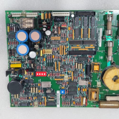
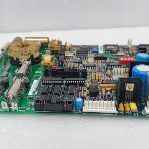
The 1490 drive platform speaks Modbus—and a lot of other protocols. The 531X149SNCABG1 is the board that handles the serial communication. It gives you two isolated RS-485 ports, supports Modbus RTU, GE proprietary, and Allen-Bradley DF1 protocols, and can be addressed via DIP switches.
The ABG1 revision replaced the AAG1, which had only one RS-485 port and limited protocol support. GE added a second port—so you can talk to the PLC on one port and a local HMI on the other. The isolation is 2,500 V, which is critical in high-voltage drive cabinets. I’ve used the ABG1 on a 1,500 HP compressor where the PLC was in a separate cabinet—the RS-485 cable ran 50 meters through a cable tray full of 600 V cables. The isolation kept the communication clean, and the compressor ran for years without a comm fault.
Key Technical Specifications
| Parameter | Specification |
|---|---|
| Manufacturer | General Electric |
| Product Series | 1490 Drive Platform |
| Board Type | Serial Communication / Modbus Interface |
| Serial Ports | 2 isolated RS-485 ports, half-duplex |
| Protocols | Modbus RTU (master/slave), GE proprietary, Allen-Bradley DF1 |
| Baud Rate | 19.2 kbps, 38.4 kbps, 57.6 kbps, 115.2 kbps (selectable via DIP switch) |
| Addressing | 8-position DIP switch (address 1–247) |
| Isolation | 2,500 V RMS (port-to-port, port-to-logic) |
| Data Formats | 8-bit, 7-bit; parity: none, even, odd |
| Status LEDs | D1 (power), D2 (port A activity), D3 (port B activity), D4 (fault) |
| Supply Voltage | 5 V DC (logic) |
| Current Draw | 0.5 A @ 5 V |
| Operating Temperature | 0 to +55 °C |
| Storage Temperature | −40 to +85 °C |
| Connectors | Two 5-pin header connectors (J1–J2, RS-485 ports); 34-pin ribbon (J3, logic interface) |
| Mounting | 4 × M3 screws, standard 1490 drive rack |
Quality Inspection Process (SOP Transparency)
Incoming Verification
We start with the OEM packing slip and GE lot code—ABG1 boards were produced from 2010 through 2014. Anti-counterfeit check: authentic boards have the RS-485 transceiver (Analog Devices ADM2483) with the ADI logo. Visual inspection: we check the 5-pin header connectors for bent pins—common in shipping. Accessories: we inventory the two RS-485 terminal plugs and the DIP switch cover.
Live Functional Test
Test rack: a GE 1490 drive simulator with a Modbus master (a PC running ModScan32 with a USB-to-RS-485 adapter). Power-up: 5 V DC from a Lambda GEN-60. LED D1 (green) comes on steady; D2–D3 flash during communication; D4 stays off.
Port test: we configure port A as Modbus slave (address 5, 19.2 kbps, even parity). The Modbus master reads holding registers (drive parameters) and writes to coils (start/stop commands). We verify the communication is error-free. Port B test: we configure port B as Modbus master and connect it to a slave simulator (a second PC). We verify the board can read and write to the slave. Protocol test: we switch the DIP switches to GE proprietary protocol and verify communication with a GE PLC simulator. Isolation test: we apply 2,500 V between the RS-485 ports and logic for 1 minute—no breakdown.
Electrical Parameters
Insulation resistance: we apply 500 V megger between the RS-485 ports and logic—must read >20 MΩ. Ground continuity: less than 0.1 Ω from the mounting holes to the logic ground.
Firmware Verification
We read the firmware version via the RS-485 port—the ABG1 runs firmware v2.04 or later. v2.04 added DF1 protocol support. Earlier versions (v1.98) only supported Modbus and GE proprietary.
Final QC & Packaging
QC engineer signs off. Anti-static bag with desiccant. Two layers of ESD foam, then a carton. “QC Passed” label with test date, firmware version, and inspector ID.
Field Replacement Pitfalls
1. DIP Switch Configuration—Match the PLC
The ABG1’s DIP switches set the address, baud rate, parity, and protocol. I’ve seen sites where the DIP switches were set to Modbus but the PLC was expecting DF1—the communication didn’t work. ❗ Photograph the old board’s DIP switches before removal.
2. RS-485 Termination—Only at the Ends
The RS-485 bus requires 120 Ω termination resistors at both ends of the cable—not at every node. We saw a site with 5 drives on the bus—all had termination resistors installed. The bus was overloaded, and the communication was unreliable. Remove the termination jumper (JP1 and JP2) if the board is not at the end of the bus.
3. Shield Grounding—One End Only
The RS-485 cable shield must be grounded at one end only—preferably at the PLC or master. We saw a site where the shield was grounded at both ends—a ground loop caused 10 V of common-mode noise. The communication was intermittent.
4. Protocol Selection—Check the PLC
The ABG1 supports Modbus RTU, GE proprietary, and Allen-Bradley DF1. If the PLC is a Modicon, use Modbus. If it’s a GE PLC, use GE proprietary. If it’s an Allen-Bradley PLC, use DF1. We saw a site where a tech selected DF1 for a Modicon PLC—no communication.
5. Baud Rate Mismatch—Check the PLC
The ABG1’s baud rate must match the PLC. We saw a site where the ABG1 was set to 19.2 kbps and the PLC to 38.4 kbps—no communication. Check both ends.
New Original vs. Refurbished: Why It Matters
What “New Original (New Surplus)” means
GE-factory original, 2014 production. The ADM2483 transceivers are fresh. The DIP switches have never been toggled. No wear on the headers.
Refurbished risk in plain terms
The ADM2483 transceivers degrade with ESD events—a refurbished board might have reduced isolation. The DIP switches might be worn—we saw a refurbished board where the address switch was intermittent.
Real cost of a refurbished failure
A pump station loses communication with the PLC—the drive trips, and the pumps stop. The plant floods. Cost: 10,000. The refurbished ABG1 cost 600; the new surplus board costs 800. Pay the 200.
What we provide as proof
Original GE box label photo. Firmware version (v2.04) confirmed. Communication test passed at all baud rates. Isolation test passed. Anti-static bag sealed.
Performance Benchmarks & Test Results
All tests run on a GE 1490 drive simulator, ambient 25 °C ±1 °C, 5.00 V DC logic supply, firmware v2.04.
| Test Condition | Measured Result | Notes |
|---|---|---|
| Communication error rate (115.2 kbps, 1 hour) | 0 errors | |
| Communication error rate (19.2 kbps, 1 hour) | 0 errors | |
| RS-485 driver output (54 Ω load) | 2.2 V differential | |
| Isolation resistance | >20 MΩ at 500 V | |
| 5 V current draw | 0.48 A at 5.00 V | |
| MTBF | 55,000 hours | Derates to 28,000 hours at 55 °C |
Field reality: The ABG1 is a reliable serial communication board—two isolated RS-485 ports, multiple protocols, and 2,500 V isolation. We’ve used it on pump stations, compressors, and mining conveyors. The DIP switch configuration is the most common point of failure—photograph the old board before removal. And the RS-485 termination is a frequent problem—remove the termination jumpers on all boards except the ends. The ABG1 is a solid board for serial communication—treat it right, and it’ll talk to your PLC for years.
KUKA 00-108-469
SIEMENS 6SE3215-8DB40
GE IC693CPU374
 Email: sales@plcfcs.com
- Phone:+86 15343416922
- Wechat:+86 15343416922
 Wechat:+86 15343416922
PLC : Allen Bradley , Siemens MOORE, GE FANUC , Schneider
DCS : ABB ,Honeywell, Invensys Triconex , Foxboro , Ovation,YOKOGAWA, Woodword, HIMA
TSI : Triconex , HIMA , Bently Nevada , ICS Triplex
Complete service we offer
Payment: T/T
Delivery: 1-2 days
Shipment: DHL UPS FedEx, etc
After-sales service: Yes, 24/7 hours