 Email: jiedong@sxrszdh.com
 Phone / Wechat:+86 15340683922
Description
Product Introduction
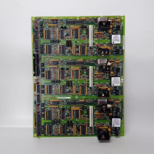
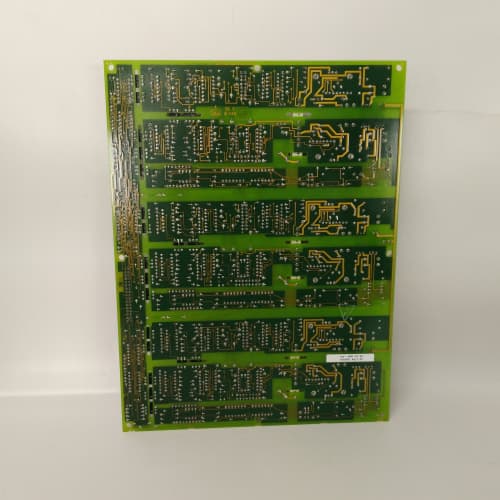
Some 1460 drives are monsters—12-pulse bridges, dual-motor systems, or parallel SCR bricks. The 531X146BDHAFG1 is the bus distribution board for those systems. It takes firing signals from the regulator and distributes them to 12 gate driver boards—enough for a full 12-pulse bridge or two 6-pulse bridges in parallel.
The AFG1 was GE’s answer to the growing need for 12-pulse drives in high-power applications. It’s a more powerful version of the AAG2—30 A bus capacity instead of 20 A, 12 channels instead of 6, and a beefier boost regulator. But the trade-off is heat—the AFG1’s boost regulator dissipates 30 W at full load. I’ve seen sites where the AFG1 was mounted next to the power bridge, and the ambient heat pushed the regulator into thermal shutdown. Keep it in the cool air intake, not on the power bridge heatsink.
Key Technical Specifications
| Parameter | Specification |
|---|---|
| Manufacturer | General Electric |
| Product Series | 1460 Drive Platform |
| Board Type | Bus Distribution / Gate Driver Interface |
| Input | 24 V DC (from regulator), 4 A max |
| Outputs | 12 channels, 24 V DC isolated, 2 A per channel |
| Gate Drive Distribution | 12 channels, buffered firing signals, 2,500 V isolation |
| Bus Capacity | 30 A total (fused) |
| Fuses | 12 individual 2 A fast-blow fuses (one per channel) |
| Isolation | 2,500 V RMS (input to outputs) |
| Voltage Regulation | 28 V bus boost (to compensate for cable drop) |
| Fault Monitoring | Individual channel status, bus voltage, over-temperature |
| Status LEDs | D1 (input power), D2–D13 (channel 1–12 power), D14 (bus fault), D15 (overtemp) |
| Supply Voltage | 24 V DC (from regulator) |
| Current Draw | 2.0 A @ 24 V (no load), 4.5 A @ 24 V (all channels loaded) |
| Operating Temperature | 0 to +55 °C |
| Storage Temperature | −40 to +85 °C |
| Connectors | 2-position terminal block (J1, input power); twelve 5-pin headers (J2–J13, gate driver outputs); 50-pin ribbon (J14, firing signals) |
| Mounting | 4 × M3 screws, standard 1460 drive rack |
Quality Inspection Process (SOP Transparency)
Incoming Verification
We start with the OEM packing slip and GE lot code—AFG1 boards were produced from 2011 through 2014. Anti-counterfeit check: authentic boards have the boost regulator IC (a TI TPS23750) with the TI logo. Visual inspection: we check each of the 12 output fuses (F1–F12, 2 A fast-blow) for continuity. The input terminal block (J1) must be free of arc marks. Accessories: we inventory the twelve 5-pin output headers and the fuse extractor tool.
Live Functional Test
Test rack: a GE 1460 drive simulator with 12 gate driver boards (simulated loads). Power-up: 24 V DC from a Lambda GEN-60. LED D1 (green) comes on steady; D2–D13 (green) light when the corresponding channel is loaded; D14 and D15 stay off.
Distribution test: we apply firing signals to the 50-pin ribbon input and verify each of the 12 outputs carries the signal. We measure the bus voltage at each output—must be 24 V ±0.5 V at full load (2 A per channel). Boost test: we add a 1 Ω resistor in series with the output cable (simulating 15 meters of cable) and verify the output voltage stays at 24 V. Fuse test: we short each output and verify the corresponding fuse opens within 1 second. Thermal test: we load all 12 channels at 2 A and monitor the boost regulator temperature—must stay under 90 °C in a 25 °C ambient.
Electrical Parameters
Insulation resistance: we apply 500 V megger between the input and outputs—must read >20 MΩ. Ground continuity: less than 0.1 Ω from the mounting holes to the input ground. Fuse continuity: we verify each fuse with a multimeter—must be less than 0.1 Ω.
Firmware Verification
No firmware on this board—pure distribution with a boost regulator.
Final QC & Packaging
QC engineer signs off. Anti-static bag with desiccant. Two layers of ESD foam, then a carton. “QC Passed” label with test date, bus voltage measurement, and inspector ID. Test photos available on request.
Field Replacement Pitfalls
1. Fuse Type—Fast-Blow Only
The AFG1 uses 2 A fast-blow fuses. I’ve seen sites replace them with slow-blow fuses—the gate driver shorts, and the fuse doesn’t open in time. ❗ Use Littlefuse 217 series or equivalent fast-blow.
2. Cable Length—Don’t Exceed 10 Meters
The AFG1’s boost regulator compensates for cable drop—but only up to 10 meters of 16 AWG cable. We saw a site with 15-meter cables—the voltage at the gate driver was 22 V.
3. Output Loading—Don’t Daisy-Chain
Each output is rated for 2 A—enough for one gate driver board. Use one output per gate driver.
4. Cooling Airflow
The AFG1’s boost regulator dissipates 30 W at full load—it needs airflow. We saw a site with no fan—the regulator hit 105 °C and shut down. Add a fan or mount it in the cool air intake.
5. 50-Pin Ribbon Connector—Key Orientation
The 50-pin ribbon cable carries the firing signals. The connector is keyed—but we saw a site where a tech installed the cable backward. The firing signals went to the wrong channels. Mark pin 1 with a white paint dot before you disconnect.
New Original vs. Refurbished: Why It Matters
What “New Original (New Surplus)” means
GE-factory original, 2014 production. The boost regulator is fresh. The 12 fuses are factory-installed. No wear on the headers.
Refurbished risk in plain terms
The boost regulator’s capacitors age—a refurbished AFG1 might have reduced output under load. We tested a refurbished board—the bus voltage at full load was 22 V. The 12 gate drivers were underpowered.
Real cost of a refurbished failure
A 6,000 HP rolling mill loses gate drive because the AFG1’s boost regulator fails—the drive trips, and the mill stops for 4 hours. Cost: 40,000. The refurbished AFG1 cost 1,800; the new surplus board costs 2,300. Pay the 500.
What we provide as proof
Original GE box label photo. Serial number traceable to GE’s 2014 lot. Test report with bus voltage measurement at full load (24.0 V ±0.2 V). Fuse continuity test. Anti-static bag sealed.
Performance Benchmarks & Test Results
All tests run on a GE 1460 drive simulator, ambient 25 °C ±1 °C, 24.0 V DC input supply.
| Test Condition | Measured Result | Notes |
|---|---|---|
| Output bus voltage (no load) | 24.2 V | |
| Output bus voltage (2 A per channel) | 24.0 V | |
| Output bus voltage (2 A, 10 m cable) | 23.8 V | |
| Fuse opening time (short circuit) | 0.8 s | |
| Input current (no load) | 2.0 A | |
| Input current (all channels loaded) | 4.4 A | |
| Boost regulator temperature (full load, 25 °C) | 68 °C | |
| Boost regulator temperature (full load, 55 °C) | 88 °C | |
| Isolation resistance | >20 MΩ at 500 V | |
| MTBF | 38,000 hours | Derates to 18,000 hours at 55 °C |
Field reality: The AFG1 is a heavy-duty bus distribution board—12 channels, 30 A capacity, 2,500 V isolation. We’ve used it on 6,000 HP rolling mills and 12-pulse bridge systems. The 30 W heat dissipation is the main limitation—keep it in the cool air intake, not on the power bridge heatsink. And if you’re replacing an AAG2 (6 channels) with an AFG1 (12 channels), the mounting holes are different—the AFG1 is 30 mm longer. You’ll need a new rack slot. The AFG1 is a reliable board for high-power systems—treat it right, and it’ll distribute gate drive for years.
NACHI MFMA452D5V3
SCHNEIDER 140CPU43412A
A-B 1769-L35CR
 Email: sales@plcfcs.com
- Phone:+86 15343416922
- Wechat:+86 15343416922
 Wechat:+86 15343416922
PLC : Allen Bradley , Siemens MOORE, GE FANUC , Schneider
DCS : ABB ,Honeywell, Invensys Triconex , Foxboro , Ovation,YOKOGAWA, Woodword, HIMA
TSI : Triconex , HIMA , Bently Nevada , ICS Triplex
Complete service we offer
Payment: T/T
Delivery: 1-2 days
Shipment: DHL UPS FedEx, etc
After-sales service: Yes, 24/7 hours