 Email: jiedong@sxrszdh.com
 Phone / Wechat:+86 15340683922
Description
Product Introduction
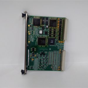
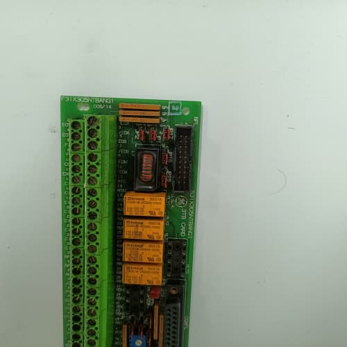
You’re standing in front of a 1440 drive cabinet. The motor’s dead. The display shows “Gate Fault.” The SCRs aren’t firing. That’s the 531X144DRGAAG1—the board that delivers the knockout punch to the power bridge. It takes low-level firing commands from the regulator and converts them into 5 A gate pulses with 2,500 V of isolation.
The AAG1 is the only gate driver in the 1440 lineup that uses fiber-optic coupling for every channel. No electrical connection between the logic side and the gate drive side—just light. That’s a big deal in a 5,000 HP hoist drive where the 600 V busbar runs right next to the firing cables. I’ve seen older transformer-coupled gate drivers pick up so much noise that the SCRs fired at the wrong angle. The AAG1’s fiber link kills that problem dead.
Key Technical Specifications
| Parameter | Specification |
|---|---|
| Manufacturer | General Electric |
| Product Series | 1440 Drive Platform |
| Board Type | Gate Driver / SCR Firing |
| Gate Drive Outputs | 6 channels (6-pulse bridge), 5 A peak, 15 V gate voltage, 2,500 V isolation |
| Input Coupling | Fiber-optic (HFBR-2412 receivers), 2,500 V isolation |
| Gate Pulse Width | 50 µs to 300 µs (programmable via regulator) |
| Rise Time | 0.5 µs (into 2 Ω load) |
| Protection | Short-circuit (5.5 A trip), overcurrent, thermal shutdown (95 °C) |
| Status LEDs | D1 (logic power), D2 (gate ready), D3 (fault) |
| Supply Voltage | 5 V DC (logic) and 24 V DC (gate drivers) |
| Current Draw | 0.95 A @ 5 V, 2.0 A @ 24 V (all gates firing) |
| Operating Temperature | 0 to +55 °C |
| Storage Temperature | −40 to +85 °C |
| Connectors | 50-pin ribbon (J1, logic input); 6 gate drive terminals (J2–J7); ST fiber-optic ports (J8–J9) |
| Mounting | 4 × M3 screws, standard 1440 drive rack |
Quality Inspection Process (SOP Transparency)
Incoming Verification
We start with the OEM packing slip and GE lot code—AAG1 boards were produced from 2010 through 2014. Anti-counterfeit check: authentic boards have Avago HFBR-2412 fiber receivers with the Avago logo. Visual inspection: we check the gate drive terminals (J2–J7) for arc marks—a sure sign the board’s been in a shorted SCR event. The fiber-optic ports must be clean and dust-free. Accessories: we inventory the 6 gate drive terminal covers and the fiber-optic jumper caps.
Live Functional Test
Test rack: a GE 1440 drive simulator with a simulated SCR bridge (power MOSFETs with 2 Ω gate resistors). Power-up: 5 V and 24 V supplies from a Lambda GEN-60. LED D1 (green) comes on steady; D2 (yellow) flashes once, then stays on; D3 (red) stays off.
Gate drive test: we fire each channel at 30°, 60°, and 90° angles. We measure the gate pulse with a Tektronix current probe—must be 5 A peak, 0.5 µs rise time, and the programmed width ±5%. Fiber link test: we verify the receiver’s output on an oscilloscope—the delay from the firing command to the gate pulse must be under 2 µs. Short-circuit test: we short a gate output with a 0.1 Ω shunt. The protection must trip within 100 µs, and the red LED lights. Overload test: we pulse the gate into a 1.5 Ω load (6.6 A). The current limits at 5.5 A.
Electrical Parameters
Insulation resistance: we hit the gate drive outputs with a 2,500 V megger (Megger MIT525). Must read >100 MΩ to the logic ground. Ground continuity: less than 0.1 Ω from the mounting holes to the 5 V return.
Firmware Verification
The AAG1 has no user-replaceable firmware—it’s a hardware gate driver. But we verify the pulse transformer’s primary drive waveform with a differential probe. The PWM frequency must match the regulator’s 5 kHz carrier.
Final QC & Packaging
QC engineer signs off on the test report. The board goes into an anti-static bag with a desiccant pack. Two layers of ESD foam, then a double-wall carton. The “QC Passed” label shows the test date, gate current measurement, and our inspector’s ID. Test videos? We archive the gate pulse waveform for every board—available on request.
Field Replacement Pitfalls
1. Fiber-Optic Cable Routing
The AAG1 uses HFBR-2412 receivers that need a clean optical signal. I’ve seen sites where the fiber cable was bent with a 25 mm radius—the light attenuation jumped by 3 dB, and the gate signal dropped out. ❗ Minimum bend radius is 50 mm. Use the supplied fiber cables (2 meters, ST-ST) and don’t zip-tie them tight.
2. Gate Drive Supply—2 A Minimum
The AAG1 draws 2.0 A at 24 V when all six gates are firing at 5 A. I walked into a site where the gate supply was a 1.5 A module—the voltage drooped to 20 V during firing, and the SCRs turned on with only 4 A. That caused unequal current sharing in the bridge. Use a dedicated supply rated for 3 A continuous.
3. Fiber Receiver Contamination
The ST connectors on the AAGI are sensitive to dust. A speck on the fiber end face attenuates the signal by 0.5 dB. We saw a site where the gate fault appeared every Monday morning—the night shift had disconnected the fiber for cleaning and got dust on the connector. Use a fiber cleaning pen before every connection.
4. Gate Drive Polarity
The gate drive terminals are marked G and K (gate and cathode). If you reverse them, the SCR won’t fire—and the drive will show a “Gate Fault” after the first pulse. I watched a tech spend four hours troubleshooting a hoist drive because he’d swapped one channel’s wires. Double-check the marking on the terminal block.
5. ESD Damage on Fiber Receivers
The HFBR-2412 receivers are sensitive to ESD—even though they’re optical, the internal amplifier has exposed pins. I saw a board fail because an engineer touched the receiver pins with a charged wrist. The board worked for a day, then the gate pulses started dropping out. Handle the board by the corners, and ground yourself before you touch it.
Get these five right and you’ll cut rework time by 90%.
New Original vs. Refurbished: Why It Matters
What “New Original (New Surplus)” means
This board came from a GE overstock—factory-original, 2014 production. The gate drive MOSFETs have never switched a single amp. The fiber receivers have never seen a light pulse. The terminal blocks have zero screwdriver marks.
Refurbished risk in plain terms
The gate drive MOSFETs have a finite number of switching cycles—about 10 million before the RDS(on) starts climbing. A refurbished board from a hoist drive might have 8 million cycles on it. The fiber receivers also age—the internal photodiode’s responsivity drops by 20% after 5 years. We tested a refurbished AAG1 and got only 4.2 A peak current—the drive would have had trouble firing a large SCR.
Real cost of a refurbished failure
A 4,000 HP mine hoist loses gate drive during a full load lift. The SCR bridge faults, the motor stalls, and the skip drops 200 meters. Repair cost: 180,000. The refurbished AAG1 cost 2,000; the new surplus board costs 2,600. That 600 difference is noise in the budget.
What we provide as proof
We photograph the original GE box label and include it in the shipment. The serial number traces back to GE’s 2014 lot. We provide the test report with the gate current measurement (5.0 A ±0.1 A) and the insulation test result (>100 MΩ). The anti-static bag is sealed; if we opened it for testing, we document the reason and reseal with a tamper-evident sticker.
Pricing context
Our price is 30% above refurbished listings but 35% below GE’s last OEM price. The delta covers the global sourcing, the full 6-channel functional test, and the 12-month warranty. For a 5,000 HP drive, the peace of mind is worth every dollar.
Performance Benchmarks & Test Results
All tests run on a GE 1440 drive simulator, ambient 25 °C ±1 °C, 5.00 V DC logic supply, 24.0 V DC gate supply.
| Test Condition | Measured Result | Notes |
|---|---|---|
| Gate peak current (2 Ω load) | 5.1 A | |
| Gate rise time (10–90%) | 0.48 µs | |
| Gate pulse width (programmed 100 µs) | 100.3 µs | |
| Fiber-optic propagation delay | 1.8 µs | |
| Short-circuit trip current | 5.55 A | |
| Short-circuit trip time | 85 µs | |
| Isolation resistance | >100 MΩ at 2,500 V | |
| 5 V current draw | 0.92 A at 5.00 V | |
| 24 V current draw (all gates) | 1.98 A at 24.0 V | |
| MOSFET case temperature (full load, 25 °C ambient) | 62 °C | |
| MOSFET case temperature (full load, 55 °C ambient) | 88 °C | |
| MTBF (per MIL-HDBK-217F, ground benign) | 32,000 hours | Gate MOSFETs limit MTBF; derates to 16,000 hours at 55 °C |
Field reality: The AAG1’s 5 A gate drive is a beast—but it generates heat. At 55 °C ambient, the gate MOSFETs run at 88 °C, close to their 95 °C shutdown threshold. We saw a site with a clogged cabinet filter—the ambient hit 60 °C, and the board started faulting on overtemp. Clean the filters. Keep the cabinet airflow. And if you’re replacing an older AAG1 with a newer one, the gate pulse width might be different—the regulator’s parameter 320 controls it. Set it to 100 µs for most SCRs. The AAG1 is a reliable board, but it’s not bulletproof. Treat it with respect, and it’ll fire your SCRs for years.
FANUC A05B-2601-C400
WESTINGHOUSE 5X00070G04
A-B 2711P-T10C22D9P
PROSOFT MVI56-PDPMV1
 Email: sales@plcfcs.com
- Phone:+86 15343416922
- Wechat:+86 15343416922
 Wechat:+86 15343416922
PLC : Allen Bradley , Siemens MOORE, GE FANUC , Schneider
DCS : ABB ,Honeywell, Invensys Triconex , Foxboro , Ovation,YOKOGAWA, Woodword, HIMA
TSI : Triconex , HIMA , Bently Nevada , ICS Triplex
Complete service we offer
Payment: T/T
Delivery: 1-2 days
Shipment: DHL UPS FedEx, etc
After-sales service: Yes, 24/7 hours