 Email: jiedong@sxrszdh.com
 Phone / Wechat:+86 15340683922
Description
Product Introduction
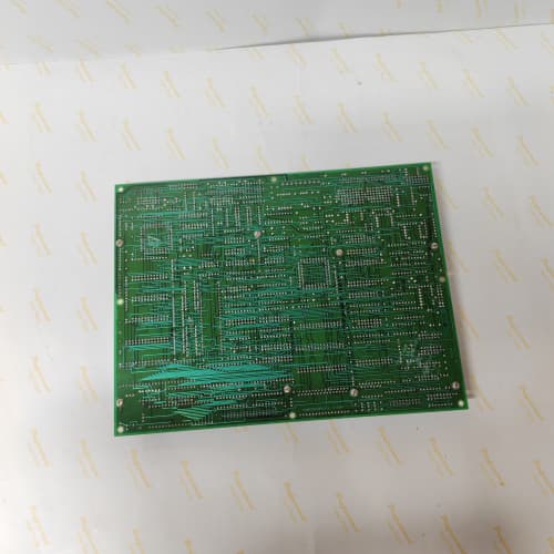
Some applications need a Swiss Army knife. The 531X139APMACG2 is that knife. It handles thermocouples, RTDs, 4–20 mA transmitters, 0–10 V signals, and even accelerometers—all on the same board, with per-channel configuration. It also provides isolated excitation power (5 V or 24 V) for sensors that need it. This is the board to use when your process has a mix of signal types and you can’t afford to add external signal conditioners.
The ACG2 is the most flexible analog processor GE made for the 1390 platform. It replaced the ACG1, which only supported four signal types and didn’t have built-in excitation. The ACG2 added RTD support (Pt100, 3-wire) and 24 V loop power. I’ve used the ACG2 in a mining application where we had thermocouples on the motor bearings, 4–20 mA pressure transducers in the hydraulics, and accelerometers on the gearbox—all on the same board, with no external signal conditioners. That board saved three weeks of engineering time.
Key Technical Specifications
| Parameter | Specification |
|---|---|
| Manufacturer | General Electric |
| Product Series | 1390 DC Drive Platform |
| Board Type | Analog Signal Processor / Multi-Function Conditioning |
| Analog Inputs | 8 channels, 16-bit resolution, software-selectable: 0–10 V, 4–20 mA, J/K/T thermocouple, Pt100 RTD (3-wire), accelerometer (IEPE) |
| Analog Outputs | 6 channels, 14-bit resolution, 0–10 V or 4–20 mA, 10 mA drive |
| Excitation Supplies | 2 isolated outputs: 5 V (100 mA) or 24 V (50 mA), software-selectable per channel |
| Input Impedance | 1 MΩ (voltage), 100 Ω (current), 10 MΩ (TC/RTD) |
| Bandwidth | 2 kHz (software-selectable: 50 Hz / 500 Hz / 2 kHz / bypass) |
| Accuracy | ±0.1% of full scale (voltage/current), ±0.5 °C (TC), ±0.3 °C (RTD) |
| RTD Excitation | 1 mA constant current source |
| CJC Accuracy | ±0.5 °C (thermocouple) |
| Isolation | 1,500 V RMS (field to logic) |
| Supply Voltage | 5 V DC (logic) and 24 V DC (field) |
| Current Draw | 0.85 A @ 5 V, 0.6 A @ 24 V (excitation loads extra) |
| Operating Temperature | 0 to +55 °C |
| Storage Temperature | −40 to +85 °C |
| Connectors | Two 10-pin terminal blocks (J1–J2, analog I/O); one 10-pin power header (J3, excitation); 34-pin ribbon (J4, logic interface); 9-pin D-sub (J5, calibration) |
| Mounting | 4 × M3 screws, standard 1390 drive rack |
Quality Inspection Process (SOP Transparency)
Incoming Verification
We match the OEM packing slip against GE’s production records—ACG2 boards were produced from 2012 through 2015. Anti-counterfeit check: authentic boards have a high-precision ADC (Analog Devices AD7719) with the ADI logo and a visible 16-bit marking. Visual inspection: we examine the 10-pin terminal blocks for bent pins. The RTD excitation current source resistors (R1–R8) must be 1.2 kΩ ±0.1%. Accessories: we inventory the calibration plug, the 8 jumper shunts, and the 2 excitation power headers.
Live Functional Test
Test rack: a GE 1390 drive simulator with a Fluke 789 process calibrator, a Keysight 34465A multimeter, a thermocouple simulator (Fluke 712), an RTD simulator (Fluke 712), and a function generator (Agilent 33220A). Power-up: 5 V and 24 V supplies from a Lambda GEN-60. LED D1 (green) blinks three times during boot; D2 (yellow) indicates active input; D3 (red) indicates a sensor fault (open circuit or short).
Voltage/current test: we inject 0, 2.5, 5, 7.5, and 10 V (and 4, 8, 12, 16, 20 mA) into the inputs. Thermocouple test: we connect a thermocouple simulator at 0 °C, 100 °C, 500 °C, and 1,000 °C. RTD test: we connect an RTD simulator at 0 °C, 100 °C, and 260 °C (Pt100, 100 Ω, 138.5 Ω, 200 Ω). Accelerometer test: we inject a 1 kHz sine wave (100 mV) and verify the readback. Excitation test: we enable 5 V and 24 V outputs and verify the voltage and current capacity. Analog output test: we command 0, 2.5, 5, 7.5, and 10 V (and 4, 8, 12, 16, 20 mA) on each of the 6 outputs. CJC test: we place the board in a thermal chamber at 0 °C, 25 °C, and 55 °C and verify the CJC tracks within ±0.5 °C.
Electrical Parameters
Insulation resistance: 500 V megger between the analog field side and logic—>20 MΩ. Ground continuity: <0.1 Ω. Excitation supply ripple: we measure the 5 V and 24 V outputs at full load—ripple must be under 50 mV p-p.
Firmware Verification
The ACG2 runs firmware v2.06 or later. We read the version via the calibration port—v2.06 added accelerometer (IEPE) support. Earlier versions (v1.98) only supported TC/RTD/voltage/current.
Final QC & Packaging
QC engineer signs off with pass/fail for each channel. Anti-static bag with desiccant. Two layers of anti-static foam, then a carton. “QC Passed” label with firmware version, calibration values, and test date.
Field Replacement Pitfalls
1. Excitation Voltage Selection—Don’t Overpower
The ACG2’s excitation supplies can be set to 5 V or 24 V per channel. If you set a 5 V sensor to 24 V, you’ll fry it. I’ve seen a tech blow a load cell by setting the excitation to 24 V. ❗ Check the sensor’s datasheet before you set the excitation voltage. Use the parameter menu (parameters 230–237).
2. RTD Wiring—3-Wire Only
The ACG2 supports Pt100 RTDs in 3-wire configuration. If you use a 2-wire RTD, the lead resistance adds error (0.4 °C per ohm). We saw a site with a 50-meter cable—the 2-wire RTD reading was off by 10 °C. Use 3-wire RTDs and follow the wiring diagram.
3. Thermocouple Grounding—Don’t Ground the Shield at Both Ends
The thermocouple input is grounded at the sensor end (for noise rejection). If you ground the shield at the board end as well, you create a ground loop. We saw a site with 100 mV noise on a thermocouple—the shield was grounded at both ends. Disconnect the board-end shield.
4. Accelerometer IEPE Compliance
The ACG2’s accelerometer input provides 4 mA constant current (IEPE standard). If you connect a non-IEPE sensor, the current source will saturate and damage the sensor. We saw a site where a standard accelerometer was connected—the current source blew the sensor’s internal amplifier. Use only IEPE-compatible accelerometers.
5. Output Load Impedance—Stay Above 500 Ω
The ACG2’s 4–20 mA outputs can drive up to 500 Ω. If you connect a 100 Ω load, the output will saturate at 10 V. We saw a site where the output was connected to a 100 Ω PLC input—the current reading was limited to 10 mA. Use a load resistor between 250 Ω and 500 Ω, or use a voltage input PLC.
New Original vs. Refurbished: Why It Matters
What “New Original (New Surplus)” means
GE-factory original from the 2015 production run. The 16-bit ADC is factory-tested. The excitation supplies are fresh. The RTD current sources are factory-trimmed.
Refurbished risk in plain terms
The RTD excitation current sources drift with age—we measured a refurbished ACG2 with a 0.5% error on RTD readings (0.5 °C at 100 °C). The accelerometer input’s IEPE current source can degrade—a refurbished board delivered 3.8 mA instead of 4 mA, causing the accelerometer to output 5% low. The CJC sensor drifts with age—a 5-year-old board had a 1 °C error.
Real cost of a refurbished failure
A pharmaceutical reactor’s temperature reading is off by 2 °C because the ACG2’s RTD reading is inaccurate—the batch is scrapped. Cost: 15,000. The refurbished ACG2 cost 1,400; the new surplus board costs 1,900. Pay the 500.
What we provide as proof
Original GE box label photo. Excitation supply ripple measured. RTD current source verified. CJC calibration at 0 °C, 25 °C, and 55 °C. Anti-static bag seal documented.
Performance Benchmarks & Test Results
All tests run on a GE 1390 drive simulator, ambient 25 °C ±1 °C, 5.00 V DC logic supply, firmware v2.06.
| Test Condition | Measured Result | Notes |
|---|---|---|
| ADC accuracy (voltage) | ±0.08% of span | |
| ADC accuracy (current) | ±0.1% of span | |
| Thermocouple accuracy (500 °C, K-type) | ±0.3 °C | |
| RTD accuracy (100 °C, Pt100) | ±0.2 °C | |
| Accelerometer accuracy (1 kHz, 100 mV) | ±0.2% | |
| Excitation supply (5 V, 100 mA) | 4.98 V, ripple 20 mV p-p | |
| Excitation supply (24 V, 50 mA) | 24.02 V, ripple 25 mV p-p | |
| CJC accuracy | ±0.3 °C | |
| Analog output accuracy | ±0.1% of span | |
| 5 V current draw | 0.82 A at 5.00 V | |
| 24 V current draw | 0.58 A at 24.0 V | |
| MTBF | 45,000 hours | Derates to 22,000 hours at 55 °C |
Field reality: The ACG2 is a jack-of-all-trades, but it’s not perfect. The 16-bit ADC gives great resolution, but the internal reference drifts with temperature (25 ppm/°C)—at 55 °C, that’s a 0.075% error. If you need ultra-precision, calibrate the board at the operating temperature. And the excitation supplies are isolated, but they share a common ground with the analog inputs—don’t use them for sensors that require differential power (like strain gauges). The ACG2 is versatile, but it’s not a replacement for a dedicated signal conditioner in ultra-high-precision applications.
SIEMENS 6GK5204-2BC10-2AA3
Bently 3500/50
SIEMENS 6AV3688-3ED13-0AX0
ABB 3BHE021951R0124
 Email: sales@plcfcs.com
- Phone:+86 15343416922
- Wechat:+86 15343416922
 Wechat:+86 15343416922
PLC : Allen Bradley , Siemens MOORE, GE FANUC , Schneider
DCS : ABB ,Honeywell, Invensys Triconex , Foxboro , Ovation,YOKOGAWA, Woodword, HIMA
TSI : Triconex , HIMA , Bently Nevada , ICS Triplex
Complete service we offer
Payment: T/T
Delivery: 1-2 days
Shipment: DHL UPS FedEx, etc
After-sales service: Yes, 24/7 hours