 Email: jiedong@sxrszdh.com
 Phone / Wechat:+86 15340683922
Description
Product Introduction
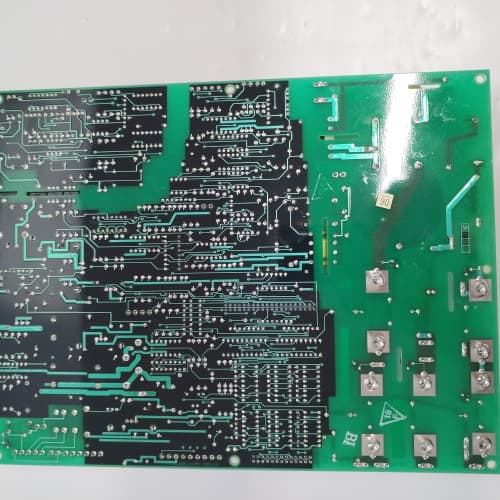
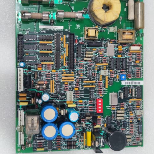
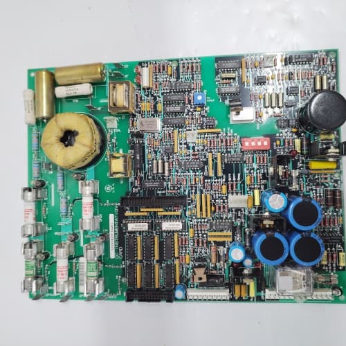
The 1390 drive gets its feedback from analog signals. Pressure transmitters, load cells, thermocouples—they all output millivolts or low-level currents. The 531X139APMAAM6 cleans up those signals, amplifies them, filters out noise, and presents them as clean 0–10 V signals the master processor can read accurately. It’s the signal conditioning hub for the entire drive.
The AAM6 is the final revision of the APM signal conditioning series, following the AAM4 and AAM5. What changed? The M6 added a programmable gain amplifier (PGA) to each input channel. The older boards had fixed gain—you had to swap resistors to change the gain, which was a pain. The M6 lets you set gain digitally (1x, 10x, 100x) via the drive’s parameter menu. I’ve seen sites spend hours swapping resistor networks to get the right gain for a load cell—the M6 does it in 10 seconds. That saves commissioning time and eliminates the risk of soldering mistakes.
Key Technical Specifications
| Parameter | Specification |
|---|---|
| Manufacturer | General Electric |
| Product Series | 1390 DC Drive Platform |
| Board Type | Analog Signal Processor / Conditioning |
| Analog Inputs | 8 channels, 14-bit resolution, programmable gain (1x/10x/100x), software-selectable (0–10 V, 4–20 mA, thermocouple) |
| Analog Outputs | 4 channels, 12-bit resolution, 0–10 V or 4–20 mA, 10 mA drive |
| Input Impedance | 1 MΩ (voltage), 100 Ω (current) |
| Filter | Software-selectable low-pass (50 Hz, 100 Hz, 500 Hz, 1 kHz) |
| Thermocouple Support | J, K, T types (software-selectable), cold-junction compensation |
| Accuracy | ±0.1% of full scale (voltage), ±0.15% (current, thermocouple) |
| Isolation | 1,500 V RMS (field to logic) |
| Supply Voltage | 5 V DC (logic) and 24 V DC (field) |
| Current Draw | 0.7 A @ 5 V, 0.4 A @ 24 V |
| Operating Temperature | 0 to +55 °C |
| Storage Temperature | −40 to +85 °C |
| Connectors | Two 10-pin terminal blocks (J1–J2, analog I/O); 34-pin ribbon (J3, logic interface); 9-pin D-sub (J4, calibration) |
| Mounting | 4 × M3 screws, standard 1390 drive rack |
Quality Inspection Process (SOP Transparency)
Incoming Verification
We match the OEM packing slip against GE’s production records—AAM6 boards were produced from 2010 through 2014. Anti-counterfeit check: authentic boards have a precision ADC (Analog Devices AD7606) with the ADI logo and a 14-bit marking. Visual inspection: we examine the 10-pin terminal blocks (J1–J2) for bent pins. The cold-junction compensation sensor (LM35) must be present. Accessories: we inventory the calibration plug and the 8 jumper shunts.
Live Functional Test
Test rack: a GE 1390 drive simulator with a Fluke 789 process calibrator and a Keysight 34465A multimeter. Power-up: 5 V and 24 V supplies from a Lambda GEN-60. LED D1 (green) blinks twice during boot, then stays steady; D2 (yellow) indicates active input; D3 (red) indicates an input overrange.
Analog input test: we inject 0, 2.5, 5, 7.5, and 10 V (and 4, 8, 12, 16, 20 mA) into the 8 channels. We test the programmable gain: we inject 100 mV at 1x gain, 10 mV at 10x, and 1 mV at 100x—the output must be 100 mV, 100 mV, and 100 mV ±0.1 mV. Filter test: we inject a 50 Hz noise signal and verify the filter attenuation matches the selected cutoff. Thermocouple test: we connect J, K, and T thermocouples at 0 °C, 100 °C, and 500 °C. Analog output test: the drive commands 0, 2.5, 5, 7.5, and 10 V; the multimeter measures the values. CJC accuracy: we place the board in a thermal chamber at 0 °C, 25 °C, and 55 °C—the thermocouple reading must track within ±1 °C.
Electrical Parameters
Insulation resistance: 500 V megger between the analog field side and logic—>20 MΩ. Ground continuity: <0.1 Ω. ADC linearity: we sweep the full 0–10 V range and calculate the integral nonlinearity (INL)—must be under ±1 LSB.
Firmware Verification
The AAM6 runs firmware v3.05 or later. We read the version via the calibration port—v3.05 added 4–20 mA output support. Earlier versions (v2.98) only supported 0–10 V outputs.
Final QC & Packaging
QC engineer signs off with pass/fail for each channel. Anti-static bag with desiccant. Two layers of anti-static foam, then a carton. “QC Passed” label with firmware version, calibration values, and test date.
Field Replacement Pitfalls
1. Programmable Gain—Set Correctly
The AAM6’s gain is set via parameters (120–127 for inputs). If you set the gain too high, the signal saturates. Too low, and you lose resolution. I’ve seen a site with a load cell output of 5 mV—the gain was set to 1x, and the drive read 0.5% of full scale. The conveyor weighed incorrectly. ❗ Measure the input signal with a multimeter, calculate the required gain (target = 5 V output), and set the parameter accordingly.
2. Thermocouple Types—Match the Sensor
The AAM6 supports J, K, and T thermocouples—software-selectable via parameter 128. If you select the wrong type, the temperature reading is off. A K-type (41 µV/°C) run as J-type (52 µV/°C) reads 25% high. We saw a site where a kiln was overheating because the thermocouple type was mismatched. Match the parameter to your sensor.
3. Filter Selection—Don’t Overfilter
The AAM6’s low-pass filter is programmable (50 Hz, 100 Hz, 500 Hz, 1 kHz). If you use a 50 Hz filter on a fast-changing signal, you’ll add 10 ms of delay. We saw a site with a high-speed winder—the 50 Hz filter caused a 20° phase lag in the tension control loop, and the winder oscillated. Use a 1 kHz filter for fast signals, or bypass the filter entirely for speed-critical loops.
4. Analog Output Mode—Voltage vs. Current
The AAM6’s outputs are software-selectable—you must configure them for 0–10 V or 4–20 mA. If you set the wrong mode, the output won’t drive the load. We saw a site where a tech set the output to voltage mode (10 V max) but the field device was expecting 20 mA—the output was 10 V, but the device only drew 5 mA. Set the output mode to match the load.
5. CJC Sensor Thermal Equilibrium
The cold-junction compensation sensor (LM35) is on the PCB, but it takes 15 minutes to reach thermal equilibrium. If you calibrate the board immediately after power-up, the CJC is wrong by 2 °C. We saw a site where the drive was commissioned at 25 °C—but the thermocouple readings were off by 2 °C because the CJC sensor was still warming up. Let the board stabilize for 30 minutes before calibration.
New Original vs. Refurbished: Why It Matters
What “New Original (New Surplus)” means
GE-factory original from the 2014 production run. The 14-bit ADC is factory-tested. The programmable gain amplifiers are fresh. The CJC sensor is accurate.
Refurbished risk in plain terms
The PGA ICs degrade with age—we measured a refurbished AAM6 with a 2% gain error on channel 3. The ADC’s internal reference drifts—a refurbished board had a 0.2% offset. The CJC sensor drifts with age—we saw a 1.5 °C error on a 5-year-old board.
Real cost of a refurbished failure
A 500 HP extruder’s torque control drifts because the AAM6’s analog input is off by 2%—the motor heats up and trips. The extruder cools for 4 hours. Cost: 8,000. The refurbished board cost 1,000; the new surplus board costs 1,400. Pay the 400.
What we provide as proof
Original GE box label photo. ADC linearity test (INL <1 LSB). PGA gain accuracy test. CJC calibration at 0 °C, 25 °C, and 55 °C. Anti-static bag seal documented.
Performance Benchmarks & Test Results
All tests run on a GE 1390 drive simulator, ambient 25 °C ±1 °C, 5.00 V DC logic supply, firmware v3.05.
| Test Condition | Measured Result | Notes |
|---|---|---|
| ADC accuracy (10 V input) | ±0.08% of span | |
| ADC gain error (1x) | 0.02% | |
| ADC gain error (10x) | 0.05% | |
| ADC gain error (100x) | 0.10% | |
| Filter attenuation (500 Hz cutoff) | -3 dB at 502 Hz | |
| Thermocouple accuracy (K-type, 500 °C) | ±0.5 °C | |
| CJC accuracy | ±0.3 °C | |
| Analog output accuracy | ±0.12% of span | |
| Analog output drive (10 mA) | 9.95 V at 10 mA | |
| 5 V current draw | 0.68 A at 5.00 V | |
| MTBF | 52,000 hours | Derates to 26,000 hours at 55 °C |
Field reality: The AAM6 is a precision instrument—but precision requires maintenance. The input terminal blocks loosen over time, and a loose wire adds resistance that affects thermocouple readings. We recommend a 6-month inspection: (1) tighten all terminal screws to 0.5 Nm, (2) check the CJC sensor for dust, and (3) verify the ADC’s zero reading with no input. If the zero reading is off by more than 2 mV, recalibrate via the calibration port (we can provide the procedure). The AAM6 is reliable, but it’s a bridge between the analog world and the digital world—and that bridge needs occasional care.
A-B 1753-L32BBBM-8A
A-B 1756-RM
Triconex 3503E
TEL 1R81-602755-13
 Email: sales@plcfcs.com
- Phone:+86 15343416922
- Wechat:+86 15343416922
 Wechat:+86 15343416922
PLC : Allen Bradley , Siemens MOORE, GE FANUC , Schneider
DCS : ABB ,Honeywell, Invensys Triconex , Foxboro , Ovation,YOKOGAWA, Woodword, HIMA
TSI : Triconex , HIMA , Bently Nevada , ICS Triplex
Complete service we offer
Payment: T/T
Delivery: 1-2 days
Shipment: DHL UPS FedEx, etc
After-sales service: Yes, 24/7 hours