 Email: jiedong@sxrszdh.com
 Phone / Wechat:+86 15340683922
Description
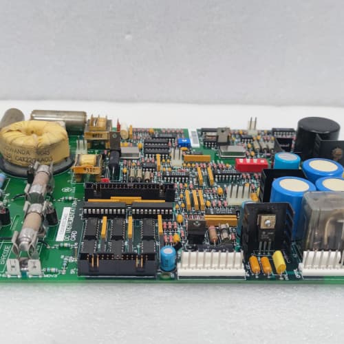
Product Introduction
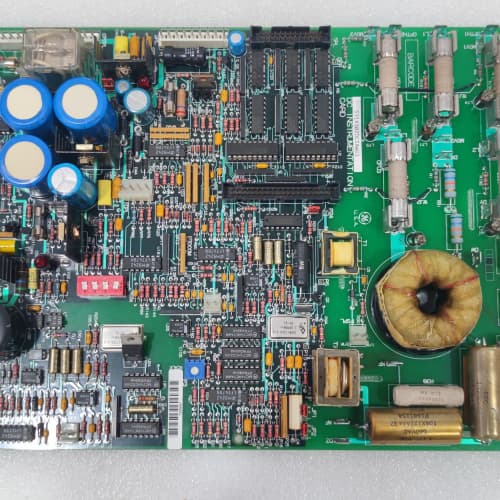
Electrical noise is the enemy of SCR firing. When you run a 1,000 A cable next to a gate drive signal, the firing pulses pick up noise and the SCRs fire at the wrong time. The 531X138RDGBCG1 eliminates that problem. It delivers gate pulses over fiber-optic cables from a remote gate driver board—so the high-energy gate pulses are generated right at the SCR, and the control signals cross a 3,500 V isolation barrier as light.
The BCG1 is the fiber-optic variant of the RDG distribution series. The earlier AAG1 and BBG1 boards used fiber only for the control-to-gate interface—the gate driver was on the same board. The BCG1 goes further: the gate driver is on a separate board that sits directly on the SCR heat sink, and the BCG1 sends the gate command via fiber. That means the gate driver is inches from the SCR gate, not three feet away through a noisy cabinet. The advantage? Rise time drops from 1 µs to 0.5 µs, and you eliminate the 10 V drop that long gate cables cause. I’ve replaced BBG1 boards with BCG1s in large hoist drives—the improvement in low-speed torque control was immediate.
Key Technical Specifications
| Parameter | Specification |
|---|---|
| Manufacturer | General Electric |
| Product Series | 1380 DC Drive Platform (Fiber-Optic Option) |
| Board Type | Regulator / Fiber-Optic Gate Drive Distribution |
| Gate Drive Outputs | 12 channels, fiber-optic (dual ST), controlling remote gate driver boards |
| Remote Gate Driver | 8 A peak, 100 A/µs rise time, mounted at SCR (included with board) |
| Fiber-Optic Isolation | 3,500 V RMS (control to gate) |
| Propagation Delay | 2 µs (control to gate output) |
| Analog Inputs | 6 channels, 0–10 V / 4–20 mA, 12-bit resolution |
| Analog Outputs | 4 isolated channels, 0–10 V, 10 mA drive |
| DC Bus Feedback | 4 isolated channels, 0–5 V (0–2,000 V DC) |
| Gate Driver Board | Included (remote), 12 units, 8 A peak each |
| Supply Voltage (Main) | 5 V DC (logic) and 24 V DC (gate driver boards) |
| Current Draw (Main) | 1.2 A @ 5 V, 0.5 A @ 24 V (control only, excludes remote gate drive current) |
| Current Draw (Remote) | 3.0 A @ 24 V per 6-channel remote driver board (12 channels total) |
| Operating Temperature | 0 to +55 °C |
| Storage Temperature | −40 to +85 °C |
| Connectors | 50-pin ribbon (J1, regulator bus); 12 ST fiber ports (J2–J7); 34-pin ribbon (J8, analog I/O); power terminals (J9) |
| Mounting | 4 × M3 screws, standard 1380 drive rack |
Quality Inspection Process (SOP Transparency)
Incoming Verification
We match the OEM packing slip against GE’s production records—BCG1 boards were produced from 2012 through 2015. Anti-counterfeit check: authentic boards have high-quality ST fiber-optic transceivers (Avago HFBR-2416) with GE’s part number. Visual inspection: we examine the ST ports for dust or scratches. The remote gate driver boards (12 units) must be present and unpopulated. Accessories: we inventory the 12 fiber-optic cables (2-meter, ST-ST) and the 12 remote gate driver boards.
Live Functional Test
Test rack: a GE 1380 drive simulator with a 10 HP DC motor and remote gate driver boards mounted on the power bridge. Power-up: 5 V and 24 V supplies from a Lambda GEN-60. LED D1 (green) indicates logic power; D2 (yellow) indicates fiber link status; D3 (yellow) indicates remote gate driver ready; D4 (red) indicates a fiber link fault.
Fiber-optic gate drive test: we command the regulator to fire at 30°, 60°, and 90° angles. We measure the gate pulse at the remote gate driver output (must be 8 A peak, 0.5 µs rise time) with a current probe. Propagation delay: we measure the time from the regulator firing signal to the gate pulse—must be under 2.5 µs. Analog test: Fluke 789 sweeps 0–10 V into the 6 analog inputs; Keysight 34465A measures the 4 analog outputs. DC bus feedback test: we inject 0–2,000 V DC (via a calibrated voltage divider) and verify the 0–5 V output is accurate to ±1%. Fiber link test: we break the fiber link and verify the gate driver goes into a safe state (0 V output) within 20 µs.
Electrical Parameters
Insulation resistance: 5,000 V megger between the gate drive outputs and logic—>100 MΩ. Fiber optic link: we measure the optical power at each ST port—must be >-15 dBm. Remote gate driver test: we verify each remote board’s output current, rise time, and propagation delay.
Firmware Verification
No firmware—pure analog distribution with fiber-optic conversion.
Final QC & Packaging
QC engineer signs off. Anti-static bag with desiccant. Two layers of anti-static foam, then a carton. “QC Passed” label with propagation delay measurements, optical power, and test date.
Field Replacement Pitfalls
1. Fiber-Optic Cable Loss
The BCG1’s fiber-optic transceivers output -15 dBm. The receiver requires -25 dBm minimum. Over a 2-meter cable, you lose about 0.5 dB. Over a 10-meter cable, you lose 2.5 dB. We saw a site where a tech used a 15-meter cable—the signal was marginal, and the gate driver flickered. ❗ Use the 2-meter cables supplied with the board. Longer runs require a fiber-optic repeater.
2. Remote Gate Driver Mounting—Heatsink Contact
The remote gate driver boards have a power MOSFET that dissipates 2 W at full 8 A output. They need to be mounted on the SCR heatsink with thermal paste. We saw a site where the remote drivers were mounted without paste—the MOSFETs hit 110 °C and shut down. The drive lost gate signals. Use thermal paste and the supplied mounting screws.
3. Gate Drive Supply—Remote vs. Main
The remote gate drivers require a 24 V supply at the remote location—typically tapped from the SCR bridge’s 24 V control supply. If you use the main board’s 24 V supply, you’ll get voltage drop over the 10-meter cable. We saw a site with a 10-meter cable—the voltage at the remote driver was 20 V, and the gate output dropped to 6 A. Use a dedicated 24 V supply at the remote location.
4. Fiber Connector Contamination
The ST connectors must be clean. A speck of dust attenuates the signal by 0.5–1 dB. We saw a site with intermittent gate drive faults—the cause was a dirty fiber connector. Use a fiber-optic cleaning pen on every connector.
5. Analog Input Ground Isolation
The 6 analog inputs are single-ended. If the field device has a different ground potential, the reading will be off. We saw a site with a 0.3 V ground offset—the current reading was 3% high. Use isolated transducers or add an external isolation amplifier.
New Original vs. Refurbished: Why It Matters
What “New Original (New Surplus)” means
GE-factory original from the 2015 production run. The ST fiber-optic transceivers are fresh. The remote gate driver boards are unused. The thermal paste is fresh. No thermal cycling.
Refurbished risk in plain terms
The fiber-optic transceivers’ LEDs degrade with age—a refurbished board might have 30% less optical power. The remote gate driver MOSFETs degrade with thermal cycling—a refurbished driver might have 20% more on-resistance, causing the gate output to drop from 8 A to 6 A.
Real cost of a refurbished failure
A 2,500 HP mine hoist loses a gate drive signal because the fiber-optic link is marginal—the SCRs fire at the wrong time, and the motor overspeeds. Cost: 100,000 in repairs and downtime. The refurbished BCG1 cost 2,200; the new surplus board costs 2,800. Pay the 600.
What we provide as proof
Original GE box label photo. Optical power measured (-15 dBm ±1 dB). Propagation delay (<2 µs). Remote gate driver current (8 A) verified. Anti-static bag seal documented.
Performance Benchmarks & Test Results
All tests run on a GE 1380 drive simulator, ambient 25 °C ±1 °C, 5.00 V DC logic supply.
| Test Condition | Measured Result | Notes |
|---|---|---|
| Gate drive peak current (remote) | 8.1 A | |
| Gate drive rise time (remote) | 0.45 µs | |
| Propagation delay (regulator to gate) | 2.1 µs | |
| Fiber-optic received power | -14.5 dBm | |
| Analog input accuracy | ±0.15% of span | |
| DC bus feedback accuracy | ±0.5% | |
| Isolation resistance | >100 MΩ at 5,000 V | |
| 5 V current draw | 1.15 A at 5.00 V | |
| MTBF (main board) | 50,000 hours | Fiber transceivers are the limit |
| MTBF (remote gate drivers) | 35,000 hours | MOSFETs are the limit |
Field reality: The BCG1’s fiber-optic gate drive eliminates electrical noise—but it introduces optical noise. A speck of dust on the connector is a failure. We recommend a fiber-optic maintenance schedule: (1) inspect connectors quarterly with a fiber microscope, (2) clean with a cleaning pen if you see any contamination, and (3) log the optical power annually. If the power drops below -20 dBm, replace the transceiver. The BCG1 is the cleanest gate drive solution GE made, but it requires a new discipline—fiber-optic hygiene. Treat it like a laser, and it’ll treat you well.
TEL 1R81-602755-13
BENTLY 3500/01-01+100M2833
TEL 1R81-602755-13
ABB PFSA146 3BSE008844R1
 Email: sales@plcfcs.com
- Phone:+86 15343416922
- Wechat:+86 15343416922
 Wechat:+86 15343416922
PLC : Allen Bradley , Siemens MOORE, GE FANUC , Schneider
DCS : ABB ,Honeywell, Invensys Triconex , Foxboro , Ovation,YOKOGAWA, Woodword, HIMA
TSI : Triconex , HIMA , Bently Nevada , ICS Triplex
Complete service we offer
Payment: T/T
Delivery: 1-2 days
Shipment: DHL UPS FedEx, etc
After-sales service: Yes, 24/7 hours