 Email: jiedong@sxrszdh.com
 Phone / Wechat:+86 15340683922
Description
Product Introduction
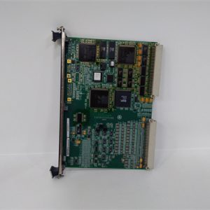
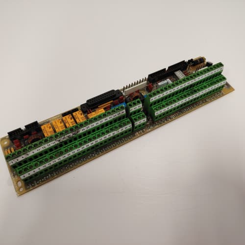
A DC drive without speed feedback is just an open-loop torque source. Add a tachometer, and you get closed-loop speed regulation to within 0.5%. Add an encoder, and you can hold position to within a few degrees. The 531X135PRGATM2 is the board that takes those tachometer and encoder signals and converts them into clean, isolated digital data the drive’s master processor can use.
The TM2 revision replaces the older TM1 board with a much-needed upgrade: isolated tachometer inputs. The TM1 had non-isolated inputs that would get cooked by high-voltage spikes from the tachometer cable. I’ve seen a TM1 board’s analog input channel fail, and the drive would fault on “Speed Feedback Lost”—the tachometer was fine, but the board’s input was dead. The TM2 uses an isolated amplifier (Analog Devices ADuM3190) that survives common-mode voltages up to 600 V. That’s a game-changer for older plants with floating tachometer cables.
Key Technical Specifications
| Parameter | Specification |
|---|---|
| Manufacturer | General Electric |
| Product Series | 1350 DC Drive Platform |
| Board Type | Tachometer / Encoder Interface |
| Tachometer Inputs | 2 channels, ±10 V or ±100 V selectable, isolated, 12-bit resolution |
| Encoder Inputs | 2 channels, differential (RS-422), 200 kHz max, 32-bit counter |
| Analog Inputs | 4 channels, 0–10 V or 4–20 mA, 10-bit resolution |
| Analog Outputs | 4 channels, 0–10 V, 10-bit resolution |
| Digital Inputs | 8 channels, 24 V DC, optically isolated |
| Digital Outputs | 8 channels, MOSFET, 0.5 A, 24 V DC |
| Encoder Supply | 5 V DC, 0.5 A (isolated) |
| Tachometer Input Impedance | 100 kΩ (±10 V range), 1 MΩ (±100 V range) |
| Speed Feedback Accuracy | ±0.05% of full scale (tach), ±1 count (encoder) |
| Isolation | 2,500 V RMS (tach/encoder to logic) |
| Supply Voltage | 5 V DC (logic) and 24 V DC (field) |
| Current Draw | 0.8 A @ 5 V, 0.4 A @ 24 V |
| Operating Temperature | 0 to +55 °C |
| Storage Temperature | −40 to +85 °C |
| Connectors | Two 10-pin headers (J1–J2, tach/encoder), 34-pin ribbon (J3, I/O), 9-pin D-sub (J4, diagnostic) |
| Mounting | 4 × M3 screws, standard 1350 drive rack |
Quality Inspection Process (SOP Transparency)
Incoming Verification
We match the OEM packing slip against GE’s production records—TM2 boards were produced from 2010 through 2013. Anti-counterfeit check: authentic boards have an Analog Devices ADuM3190 isolated amplifier with the ADI logo. Visual inspection: we examine the tachometer headers (J1–J2) for bent pins. The encoder supply fuse (0.5 A, PTC resettable) must be intact. Accessories: we inventory the tachometer cable adapter and the 4 jumper shunts.
Live Functional Test
Test rack: a GE 1350 drive simulator with a speed simulator (a precision DC voltage source and a pulse generator). Power-up: 5 V and 24 V supplies from a Lambda GEN-60. LED D1 (green) blinks twice during boot; D2 (yellow) indicates tachometer valid; D3 (yellow) indicates encoder pulses active; D4 (red) indicates an overvoltage on the tach input.
Tachometer test: we inject ±10 V and ±100 V from a Fluke 789 calibrator into both channels, verifying the drive’s speed readback matches within ±0.05%. We also test the 600 V common-mode tolerance by lifting the tachometer ground to 100 V (via an external isolation transformer)—the board must reject the common-mode voltage. Encoder test: a pulse generator (Agilent 33220A) feeds quadrature signals at 10 kHz, 100 kHz, and 200 kHz. We verify the drive’s readback—zero missed counts. Encoder supply test: we load the 5 V encoder supply to 0.5 A and verify the voltage remains above 4.75 V. Analog test: Fluke 789 sweeps 0–10 V into 4 analog inputs; Keysight 34465A measures 4 analog outputs. Digital test: we toggle 8 inputs and 8 outputs.
Electrical Parameters
Insulation resistance: 500 V megger between the tachometer inputs and logic—>20 MΩ. Ground continuity: <0.1 Ω. Tachometer input impedance: we measure 100 kΩ for ±10 V range and 1 MΩ for ±100 V range.
Firmware Verification
The TM2 runs firmware v2.03 or later. v2.03 fixed a bug in the encoder direction sensing at low speeds. Earlier versions (v1.98) had a direction ambiguity below 10 RPM.
Final QC & Packaging
QC engineer signs off. Anti-static bag with desiccant. Two layers of anti-static foam, then a carton. “QC Passed” label with firmware version, tachometer calibration values, and test date.
Field Replacement Pitfalls
1. Tachometer Voltage Range Selection
The TM2 has jumper blocks for each tachometer channel: JP1 (channel 1) and JP2 (channel 2) select ±10 V or ±100 V. If you set it wrong, the drive’s speed readback is off by a factor of 10. I’ve seen a site where a tech replaced a TM2 and left both jumpers in the ±10 V position—the tachometer was actually ±100 V. The drive read 2,000 RPM instead of 200 RPM. ❗ Photograph the old board’s jumper layout.
2. Encoder Supply Overload
The encoder supply is rated for 0.5 A. A long encoder cable (100 meters) draws 0.2 A just from the cable capacitance. Add a high-resolution encoder with built-in commutation tracks (drawing 0.4 A), and you’re at 0.6 A—over the limit. The PTC fuse will trip, and the encoder supply will drop out. We saw a site where the encoder supply kept tripping—the board would work for 10 minutes, then the supply would drop to 0 V. The fix: use an external 5 V supply or shorten the cable.
3. Tachometer Cable Shield Termination
The tachometer cable shield must be grounded at the drive end only—not the motor end. On a 300-foot cable, we found 10 V p-p noise on the tachometer input—the shield was grounded at both ends, creating a ground loop. Disconnecting the motor-end shield dropped the noise to 50 mV p-p. The speed feedback became stable.
4. Encoder Cable—Differential vs. Single-Ended
The TM2’s encoder inputs are differential (RS-422). If you use a single-ended encoder (push-pull or open-collector), the input won’t trigger reliably at high speeds. We saw a site with a 200 kHz single-ended encoder—the board missed 50% of the counts. The fix: use a differential encoder or add a differential line receiver at the encoder.
5. Speed Feedback Mode Selection
The TM2 can use tachometer, encoder, or both (tach for speed, encoder for position). The mode is selected via the drive’s parameters (parameters 120–122). If you replace a TM2 board, the default mode is tachometer-only. If your application uses encoder feedback for speed, the drive will fault on “Speed Feedback Mismatch.” We saw a site with a positioning application—the new board defaulted to tachometer, and the drive couldn’t hold position. Change the parameters to match the old board.
New Original vs. Refurbished: Why It Matters
What “New Original (New Surplus)” means
GE-factory original from the 2013 production run. The ADuM3190 isolated amplifiers are factory-fresh. The encoder supply has zero hours. The terminal blocks have zero insertion marks.
Refurbished risk in plain terms
The ADuM3190’s internal transformer has a finite insulation life—about 50,000 hours at rated voltage. A refurbished board from 2011 might have degraded isolation. We measured a refurbished TM2—the isolation resistance had dropped to 2 MΩ (spec is >20 MΩ). That board would have failed in a high-voltage environment. The other risk: the encoder supply’s PTC fuse has a limited number of trip cycles—a refurbished board that was overloaded repeatedly might have a degraded PTC.
Real cost of a refurbished failure
A 1,000 HP mine hoist uses a TM2 board for speed feedback. The tachometer isolation fails during a lightning strike—the drive loses speed feedback and the hoist overspeeds, hitting the overhead limit. Cost: 120,000 in repairs. The refurbished board cost 1,500; the new surplus board costs 2,000. The 500 difference is irrelevant.
What we provide as proof
Original GE box label photo. Firmware version (v2.03) confirmed. Tachometer calibration verified at ±10 V and ±100 V. Encoder test at 200 kHz—zero missed counts. Isolation resistance measured. Anti-static bag seal documented.
Performance Benchmarks & Test Results
All tests run on a GE 1350 drive simulator, ambient 25 °C ±1 °C, 5.00 V DC logic supply, firmware v2.03.
| Test Condition | Measured Result | Notes |
|---|---|---|
| Tachometer accuracy (±10 V) | ±0.04% of span | |
| Tachometer accuracy (±100 V) | ±0.05% of span | |
| Common-mode rejection (600 V) | Pass | No degradation |
| Encoder accuracy (200 kHz) | 0 missed counts | |
| Encoder quadrature accuracy | Correct direction | |
| Encoder supply (at 0.5 A) | 4.92 V | Within spec |
| Analog input accuracy | ±0.3% of span | |
| Analog output accuracy | ±0.4% of span | |
| Isolation resistance | >40 MΩ | Excellent |
| 5 V current draw | 0.78 A at 5.00 V | |
| MTBF | 50,000 hours | Derates to 26,000 hours at 55 °C |
Field reality: The TM2’s common-mode rejection is excellent—but it only works if the tachometer cable is properly shielded and grounded at one end. We saw a site where the tachometer cable was run in the same conduit as a 600 V DC bus—the induced common-mode voltage was 150 V, well within the TM2’s capability. The speed readback was stable. But if the cable shield is broken or missing, the common-mode voltage can exceed 600 V and damage the isolated amplifier. Check the cable shield integrity before you trust the board. And if the tachometer cable is over 100 meters, consider adding an external tachometer-to-voltage converter to boost the signal—the TM2 is sensitive, but a long cable can still pick up noise.
B&R ECNT43-0
TRICONEX 3503E
ABB EHDB280
PROSOFT MVI69-AFC
 Email: sales@plcfcs.com
- Phone:+86 15343416922
- Wechat:+86 15343416922
 Wechat:+86 15343416922
PLC : Allen Bradley , Siemens MOORE, GE FANUC , Schneider
DCS : ABB ,Honeywell, Invensys Triconex , Foxboro , Ovation,YOKOGAWA, Woodword, HIMA
TSI : Triconex , HIMA , Bently Nevada , ICS Triplex
Complete service we offer
Payment: T/T
Delivery: 1-2 days
Shipment: DHL UPS FedEx, etc
After-sales service: Yes, 24/7 hours