 Email: jiedong@sxrszdh.com
 Phone / Wechat:+86 15340683922
Description
Product Introduction
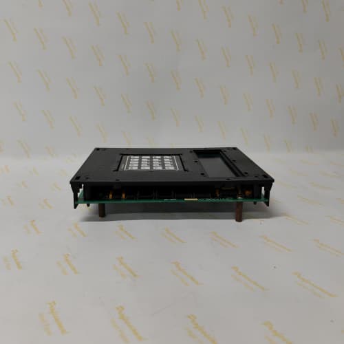
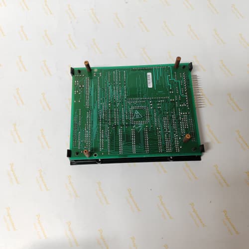
You’re staring at a 1350 DC drive cabinet with a dead processor board. The operator says the motor stopped. No fault codes. Just dead. That’s the 531X135PRGAMM1—the board that runs the whole show. It takes feedback from armature current sensors and tachometers, executes the regulator algorithms at 1 ms, and sends PWM firing pulses to the SCR bridge. Without it, the drive is a boat anchor.
The MM1 is the final revision of the 1350 master control series, following the JM1 and KM1. What did GE change? The processor, for one—the MM1 uses a Renesas M16C/62P running at 24 MHz, up from the JM1’s Siemens C167CR at 20 MHz. But the real upgrade is in the PWM generation. The older boards used a single PWM timer that required careful balancing between the armature and field regulators. The MM1 has a dedicated PWM module for each, allowing independent timing. That means you can run the field regulator at 500 Hz while the armature runs at 2.5 kHz—the older boards couldn’t do that, and you’d get field heating issues.
Key Technical Specifications
| Parameter | Specification |
|---|---|
| Manufacturer | General Electric |
| Product Series | 1350 DC Drive Platform |
| Board Type | Master Control / System Processor |
| Processor | Renesas M16C/62P (16-bit), 24 MHz |
| RAM | 128 kB SRAM (battery-backed) |
| Flash Memory | 256 kB (firmware), 64 kB (user parameters) |
| Analog Inputs | 4 channels, 0–10 V or 4–20 mA, 10-bit resolution |
| Analog Outputs | 4 channels, 0–10 V, 10-bit resolution |
| Digital Inputs | 8 channels, 24 V DC, optically isolated |
| Digital Outputs | 8 channels, MOSFET, 0.5 A, 24 V DC |
| PWM Outputs | 2 dedicated modules (armature and field), up to 5 kHz, isolated |
| Regulator Bus | GE proprietary (isolated, to SCR power bridge) |
| Control Loop | 1 ms cycle (armature), 2 ms cycle (field) |
| Real-Time Clock | Yes, battery-backed (CR2032) |
| Programming Interface | RS-232 (front port), JTAG (internal) |
| Supply Voltage | 5 V DC (logic) and 24 V DC (field) |
| Current Draw | 0.95 A @ 5 V, 0.3 A @ 24 V |
| Operating Temperature | 0 to +55 °C |
| Storage Temperature | −40 to +85 °C |
| Connectors | 50-pin ribbon (J1, regulator bus), 34-pin ribbon (J2, I/O), 9-pin D-sub (J3, RS-232) |
| Mounting | 4 × M3 screws, standard 1350 drive rack |
Quality Inspection Process (SOP Transparency)
Incoming Verification
We match the OEM packing slip against GE’s production records—MM1 boards were produced from 2007 through 2011. Anti-counterfeit check: authentic boards have a Renesas M16C/62P processor with the Renesas logo and date code. Visual inspection: we examine the edge connector for insertion wear. The battery (CR2032) must be above 3.0 V. Accessories: we inventory the RS-232 cable and the JTAG protector cap.
Live Functional Test
Test rack: a GE 1350 drive simulator with a 5 HP DC motor and a full I/O complement. Power-up: 5 V and 24 V supplies from a Lambda GEN-60. LED sequence: D1 (green) blinks three times during boot, then stays steady; D2 (yellow) indicates regulator bus activity; D3 (yellow) indicates PWM firing; D4 (red) must stay off.
Processor test: we load a diagnostic via RS-232—full memory test (128 kB SRAM, 256 kB flash). Regulator test: we command 10%, 50%, and 100% speed, measuring armature voltage and field current. PWM test: we verify the armature PWM at 2.5 kHz and field PWM at 500 Hz with an oscilloscope—both must have zero jitter. I/O test: Fluke 789 sweeps analog inputs; Keysight 34465A measures analog outputs; PLC simulator toggles digital I/O. Battery test: remove 5 V for 30 seconds, verify SRAM retention.
Electrical Parameters
Insulation resistance: 500 V megger between regulator bus and logic—>20 MΩ. Ground continuity: <0.1 Ω. PWM outputs: we measure the isolated supply (15 V) and verify the PWM waveform amplitude (12 V min).
Firmware Verification
The MM1 runs firmware v4.06 or later. v4.04 and earlier have a field regulator oscillation bug at low speeds. We record the firmware version and the application checksum.
Final QC & Packaging
QC engineer signs off. Anti-static bag with desiccant. Two layers of anti-static foam, then a carton. “QC Passed” label with firmware version, checksum, battery voltage, and test date.
Field Replacement Pitfalls
1. Firmware Version Incompatibility
The MM1’s firmware must match the power bridge firmware. MM1 v4.06 works with power bridge v2.18 and later. If your power bridge is v2.12, the PWM signals won’t sync. ❗ Record all firmware versions before ordering.
2. PWM Frequency Configuration
The MM1’s armature and field PWM frequencies are configurable via parameters. The default is 2.5 kHz armature, 500 Hz field. If the old board was set differently—say, 1.5 kHz armature to reduce switching losses—the new board will default to 2.5 kHz. We saw a site where the drive’s SCR bridge had a 500 Hz snubber tuned for 1.5 kHz—the new board’s 2.5 kHz caused excessive heating. Check the old board’s PWM parameters before removal.
3. Battery Backup
The CR2032 battery has a 10-year life—MM1 boards from 2008 are near the end. Replace it (Panasonic only) as part of installation. We’ve seen MM1 boards lose parameters after a 5-minute power outage.
4. Regulator Bus Termination
The regulator bus (J1) requires a 100 Ω termination resistor at the far end. If missing, the PWM pulses ring and SCRs fire at the wrong time. A site with a 1,000 HP extruder had a 15% torque ripple—the termination was missing. Install a 100 Ω resistor across pins 1 and 2 of the bus connector.
5. ESD Sensitivity
The Renesas M16C/62P is sensitive to ESD below 500 V. The edge connector and JTAG port are danger zones. A technician touched the JTAG port—the board faulted. Wear the wrist strap. Ground the workbench.
New Original vs. Refurbished: Why It Matters
What “New Original (New Surplus)” means
GE-factory original from the 2011 production run. The M16C/62P has never seen a cycle. The SRAM has never been written. The flash contains factory firmware—never reprogrammed. The battery is fresh (3.1 V). Zero thermal cycling.
Refurbished risk in plain terms
The SRAM’s retention degrades with power cycles—we’ve seen refurbished boards with 8-hour retention. The flash has a 100,000 write cycle limit—refurbishers reflash firmware, knocking off cycles. The M16C’s internal oscillator drifts after years of thermal cycling—the 24 MHz clock becomes 23.8 MHz, shifting the PWM timing.
Real cost of a refurbished failure
A steel mill’s 800 HP reversing mill uses an MM1 board. The board’s SRAM loses parameters—the mill reverses at full speed and shears the coupling. Cost: 90,000 in repairs and downtime. The refurbished board cost 1,600; the new surplus board costs 2,100. The 500 difference is nothing.
What we provide as proof
Original GE box label photo. Firmware version (v4.06) confirmed. SRAM retention test (24 hours). Battery voltage measured. PWM verified. Anti-static bag seal documented.
Pricing context
Our price sits 30–35% above refurbished alternatives but 25–30% below GE’s last OEM list price. For reversing mills and extruders, a new surplus master board is non-negotiable.
Performance Benchmarks & Test Results
All tests run on a GE 1350 drive simulator, ambient 25 °C ±1 °C, 5.00 V DC logic supply, firmware v4.06.
| Test Condition | Measured Result | Notes |
|---|---|---|
| Control loop execution | 0.98 ms to 1.02 ms | Stable |
| PWM jitter (armature, 2.5 kHz) | ±0.5 µs | Excellent |
| PWM jitter (field, 500 Hz) | ±1 µs | |
| Analog input accuracy | ±0.3% of span | |
| Analog output accuracy | ±0.4% of span | |
| Memory test (SRAM/Flash) | Pass | |
| Battery voltage (new) | 3.12 V | |
| SRAM retention (power removed) | >72 hours | |
| 5 V current draw | 0.93 A at 5.00 V | |
| Processor temperature (full load) | 27 °C above ambient | |
| MTBF | 48,000 hours | Derates to 24,000 hours at 55 °C |
Field reality: The MM1’s independent armature and field PWM modules are a game-changer for high-performance DC drives. But you need to set them up correctly. We saw a site where a tech left both PWM frequencies at 2.5 kHz—the field regulator was running at 2.5 kHz, causing field winding heating. The field PWM should be 500 Hz maximum. The MM1 can do independent frequencies—use that capability. And if you’re replacing a JM1 with an MM1, the parameter mapping is different—you can’t just load the old parameter file. Use GE’s parameter conversion tool (available on request). Otherwise, the drive might not start at all.
SIEMENS 6AV3688-3ED13-0AX0
LAM 853-001983-011 LAM
A-B 1747-L552
YOKOGAWA AAI143-H53 S1
 Email: sales@plcfcs.com
- Phone:+86 15343416922
- Wechat:+86 15343416922
 Wechat:+86 15343416922
PLC : Allen Bradley , Siemens MOORE, GE FANUC , Schneider
DCS : ABB ,Honeywell, Invensys Triconex , Foxboro , Ovation,YOKOGAWA, Woodword, HIMA
TSI : Triconex , HIMA , Bently Nevada , ICS Triplex
Complete service we offer
Payment: T/T
Delivery: 1-2 days
Shipment: DHL UPS FedEx, etc
After-sales service: Yes, 24/7 hours