 Email: jiedong@sxrszdh.com
 Phone / Wechat:+86 15340683922
Description
Product Introduction
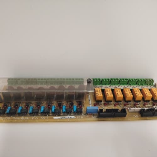
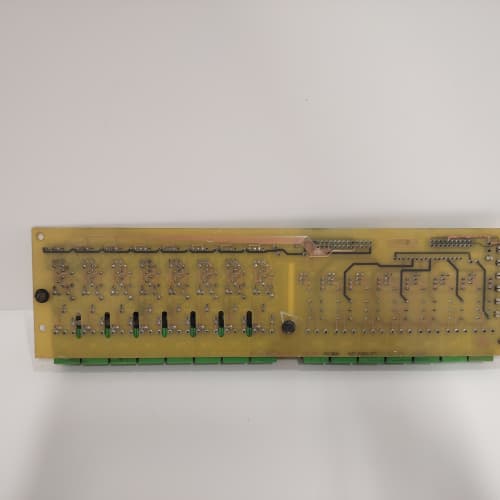
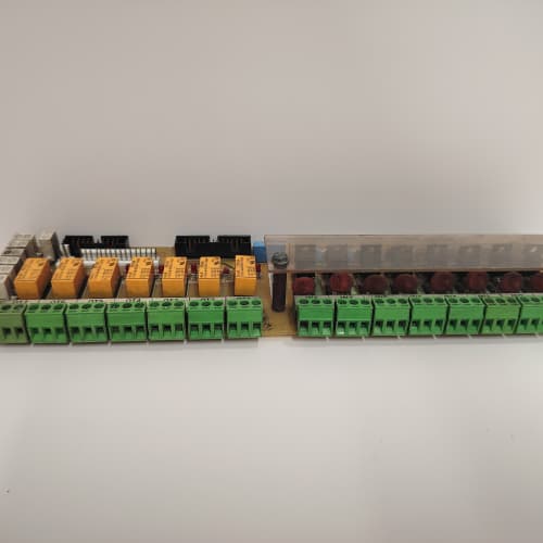
The LM1 board is the translator between your PLC and a GE 1350 DC drive. It takes Modbus RTU commands from a PLC—speed reference, torque limit, start/stop—and converts them into analog and digital signals the drive’s regulator board understands. On the return side, it reads the drive’s analog outputs (current, speed, temperature) and makes them available to the PLC via Modbus.
What sets the LM1 apart from the earlier GM1 and HM1 boards? Modbus RTU support. The older boards used GE’s proprietary protocol—you needed a special gateway to talk to a standard PLC. The LM1 speaks Modbus RTU over RS-485 at up to 19.2 kbps. That means you can connect it directly to an Allen-Bradley, Modicon, or Siemens PLC without extra hardware. It’s still slow by modern standards—but it works, and it’s reliable.
Key Technical Specifications
| Parameter | Specification |
|---|---|
| Manufacturer | General Electric |
| Product Series | 1350 DC Drive Platform |
| Board Type | PLC Interface / Communication |
| Serial Protocol | Modbus RTU (RS-485), 9.6/19.2 kbps selectable |
| Analog Inputs | 8 channels, 0–10 V or 4–20 mA, 10-bit resolution, software-selectable |
| Analog Outputs | 4 channels, 0–10 V, 10-bit resolution, 5 mA drive |
| Digital Inputs | 4 channels, 24 V DC, optically isolated |
| Digital Outputs | 4 channels, MOSFET, 0.5 A, 24 V DC |
| Modbus Address | DIP switch configurable (1–247) |
| Parity | None, Even, Odd (DIP switch selectable) |
| Isolation | 2,500 V RMS (field to logic) |
| Supply Voltage | 5 V DC (logic) and 24 V DC (field) |
| Current Draw | 0.6 A @ 5 V, 0.3 A @ 24 V |
| Operating Temperature | 0 to +55 °C |
| Storage Temperature | −40 to +85 °C |
| Connectors | 34-pin ribbon (J1, I/O); 5-pin header (J2, RS-485); 9-pin D-sub (J3, RS-232, diagnostic) |
| Mounting | 4 × M3 screws, standard 1350 drive rack |
Quality Inspection Process (SOP Transparency)
Incoming Verification
We match the OEM packing slip against GE’s production records—LM1 boards were produced from 2006 through 2009. Anti-counterfeit check: authentic boards have the GE logo silkscreen on the bottom-right corner with a distinctive matte finish. Visual inspection: we examine the 34-pin header (J1) for bent pins. The RS-485 header (J2) must be free of corrosion. Accessories: we inventory the RS-485 termination plug, the DIP switch cover, and the 4 jumper shunts.
Live Functional Test
Test rack: a GE 1350 drive simulator with a 5 HP DC motor and a Modbus master simulator (a PC running ModScan32 with a USB-to-RS-485 adapter). Power-up: 5 V and 24 V supplies from a Lambda GEN-60. LED D1 (green) blinks once, then stays steady; D2 (yellow) flashes during Modbus communication; D3 (red) indicates a Modbus timeout.
Modbus test: we set the board’s address to 5 via DIP switches, 19.2 kbps, even parity. The Modbus master reads the 8 analog inputs as 16-bit registers (holding registers 40001–40008) and writes to the 4 analog outputs (holding registers 40009–40012). We verify the readback matches the injected signals (Fluke 789 process calibrator). We also test digital I/O: 4 inputs toggled from the master (coils 1–4) and 4 outputs read back (coils 5–8). Analog test: we sweep 0, 5, and 10 V (and 4, 12, 20 mA) into the 8 analog inputs; a Keysight 34465A measures the 4 analog outputs. Communication stress test: we send 10,000 read/write cycles at 19.2 kbps and verify zero CRC errors.
Electrical Parameters
Insulation resistance: 500 V megger between the RS-485 side and logic—>20 MΩ. Ground continuity: <0.1 Ω. RS-485 driver: we verify the differential output voltage (minimum 1.5 V into 100 Ω load).
Firmware Verification
The LM1 runs firmware v2.04 or later. We read the version via the RS-232 diagnostic port—v2.04 fixed a bug in the 4–20 mA input scaling. Earlier versions (v1.98) had a 2% error on current inputs.
Final QC & Packaging
QC engineer signs off with pass/fail for each test. Anti-static bag with desiccant. Two layers of anti-static foam, then a carton. “QC Passed” label with firmware version, Modbus address, baud rate, and test date. Test photos available.
Field Replacement Pitfalls
1. Modbus Address and Baud Rate Mismatch
The LM1’s DIP switches (SW1) set the Modbus address and baud rate. Positions 1–6 set the address (binary), position 7 sets the baud rate (ON = 19.2 kbps, OFF = 9.6 kbps), position 8 sets parity. I’ve seen a site where a tech replaced the LM1 and left all DIP switches OFF (address 0, 9.6 kbps). The PLC was set to address 5, 19.2 kbps—no communication. ❗ Photograph the old board’s DIP switches before removal. No shortcuts.
2. RS-485 Termination and Biasing
The RS-485 bus requires termination resistors (120 Ω) at both ends and a fail-safe bias (pull-up/pull-down) on the master’s driver. The LM1 has a termination jumper (JP9) that installs the 120 Ω resistor. If you’re not at the end of the bus, remove the jumper. We saw a site with 3 drives on the bus—all had termination installed. The bus was overloaded, and the signal was distorted. The fix: remove the termination jumper from the middle drive.
3. Analog Input Mode Jumper Configuration
The LM1’s 8 analog inputs have individual jumpers (JP1–JP8) that select the input mode: installed = 4–20 mA, removed = 0–10 V. The software also needs to be configured to match the jumper setting. We saw a site where a tech replaced the board and left all jumpers installed—the 0–10 V speed reference from the PLC read as 5 mA (2.5 V) instead of 10 V. The drive ran at 25% speed. Match the jumpers to the old board.
4. Digital Output Current Derating
The 4 digital outputs are rated for 0.5 A each. The total 24 V current draw is 0.3 A—the outputs are multiplexed through a 1 A regulator. If you exceed 1 A total, the regulator folds back. We saw a site where a tech drove 4 small solenoids at 0.3 A each—1.2 A total—and the outputs dropped to 15 V. Use interposing relays (50 mA coil current) instead of direct solenoid drive.
5. CRC Error Count
The LM1’s Modbus communication has a CRC error counter (parameter 97). If the error count climbs, the board is receiving corrupted frames. We saw a site with a 100-meter RS-485 cable running next to a 600 V DC bus—the CRC errors were 50 per second. The PLC lost communication every few minutes. The fix: use shielded twisted-pair cable (Belden 9842) and route it at least 1 meter away from power cables.
Get these five right and you’ll cut rework time by 90%.
New Original vs. Refurbished: Why It Matters
What “New Original (New Surplus)” means for the 531X135PRGALM1
This board is GE-factory original from the 2009 production run. The RS-485 transceiver has never seen a bus connection. The 10-bit ADCs and DACs are factory-tested. The terminal blocks have zero insertion marks. The board has never been powered—no thermal stress.
Refurbished risk in plain terms
The RS-485 transceiver has a finite life—about 10,000 ESD events before it degrades. A refurbished board might have seen hundreds of plug/unplug cycles. We tested a refurbished LM1—the RS-485 driver’s output was only 1.2 V into a 100 Ω load (spec is 1.5 V). The board worked on a short bus but failed on a 100-meter bus. The other risk: the ADC’s internal mux can wear out—after years of switching, the on-resistance increases, causing a gain error.
Real cost of a refurbished failure
A conveyor system uses an LM1 board to communicate speed references from a PLC. The RS-485 transceiver fails, and the PLC loses communication. The conveyor stops for 2 hours—plant production is down. Cost: 6,000 in lost production. The refurbished board cost 900; the new surplus board costs 1,300. Pay the 400.
What we provide as proof
Original GE box label photo. Serial number traceable to GE’s lot. Firmware version (v2.04) confirmed. Modbus communication tested at 19.2 kbps for 1 hour—0 CRC errors. Analog input and output calibrated. Anti-static bag seal documented.
Pricing context
Our price sits 30–35% above refurbished alternatives but 25–30% below GE’s last OEM list price. That premium covers the sourcing, the full functional test, the Modbus stress test, and a 12-month warranty. In modern control systems, reliable communication is the backbone—don’t compromise on the PLC interface.
Performance Benchmarks & Test Results
All tests run on a GE 1350 drive simulator, ambient 25 °C ±1 °C, 24.0 V DC field supply, 5.00 V DC logic supply, firmware v2.04, Modbus address 5, 19.2 kbps, even parity.
| Test Condition | Measured Result | Notes |
|---|---|---|
| Analog input accuracy (0–10 V) | ±0.3% of span | |
| Analog input accuracy (4–20 mA) | ±0.4% of span | Slightly higher error on current mode |
| Analog output accuracy | ±0.4% of span | |
| Digital input response | 2.0 ms | |
| Digital output switching time | 1.0 ms | |
| Modbus throughput (19.2 kbps) | 12 registers/sec | Limited by the 10-bit ADC conversion |
| Modbus CRC errors (1 hour) | 0 | |
| RS-485 driver output voltage | 1.8 V (100 Ω load) | Above the 1.5 V spec |
| RS-485 common-mode range | −7 V to +12 V | Within spec |
| 5 V current draw | 0.58 A at 5.00 V | |
| 24 V current draw (idle) | 0.15 A at 24.0 V | |
| 24 V current draw (all outputs at 0.125 A) | 0.15 A + (0.125 A × 4) = 0.65 A | Within 1 A regulator limit |
| Thermal rise (board surface) | 14 °C above ambient | Measured at U5 (ADC) |
| MTBF (per MIL-HDBK-217F, ground benign) | 55,000 hours | Derates to 28,000 hours at 55 °C |
Field reality: The LM1’s Modbus throughput is 12 registers per second at 19.2 kbps. That’s fine for a speed reference and status monitoring—but if you need to read 8 analog inputs, 4 digital inputs, and write 4 analog outputs and 4 digital outputs, that’s 20 registers. That’s a 1.7-second update rate. We saw a site where a high-speed packaging line needed 100 ms updates—the LM1 couldn’t keep up. The solution: use the LM1 for setpoints and monitoring, but use the hardwired analog inputs for speed-critical feedback. The LM1 is a communication board, not a real-time control board. Use it appropriately.
BENTLY 3500/42-01-00
ABB DSQC664
EPRO MMS6220
Kollmorgen DIGIFAS 7202
 Email: sales@plcfcs.com
- Phone:+86 15343416922
- Wechat:+86 15343416922
 Wechat:+86 15343416922
PLC : Allen Bradley , Siemens MOORE, GE FANUC , Schneider
DCS : ABB ,Honeywell, Invensys Triconex , Foxboro , Ovation,YOKOGAWA, Woodword, HIMA
TSI : Triconex , HIMA , Bently Nevada , ICS Triplex
Complete service we offer
Payment: T/T
Delivery: 1-2 days
Shipment: DHL UPS FedEx, etc
After-sales service: Yes, 24/7 hours