 Email: jiedong@sxrszdh.com
 Phone / Wechat:+86 15340683922
Description
Product Introduction
The 1350 platform is GE’s workhorse for medium-voltage DC drives—up to 1,000 HP in cranes, extruders, and winders. The 531X135PRGAAM3 is how you talk to those drives from a PLC. It takes the drive’s internal signals—armature current, field voltage, speed feedback, temperature—and presents them as standard 0–10 V or 4–20 mA signals that any PLC can read. On the return side, it converts PLC commands (speed references, torque limits, start/stop) into signals the drive’s regulator board can use.
What does the “M3” revision give you? A longer part number—but more importantly, a better serial interface. The earlier M1 and M2 revisions used a 300 baud current-loop interface that was glacial and required special converters. The M3 uses RS-232 and RS-485 at up to 19.2 kbps. That’s still slow by modern standards, but it’s usable for parameter uploads and diagnostic logging. I’ve watched technicians spend hours trying to get an M1 board to communicate with a modern laptop—the M3 works with a standard USB-to-serial adapter, saving you the headache.
Key Technical Specifications
| Parameter | Specification |
|---|---|
| Manufacturer | General Electric |
| Product Series | 1350 DC Drive Platform |
| Board Type | I/O Interface / PLC Communication |
| Analog Inputs | 8 channels, 0–10 V DC or 4–20 mA, 10-bit resolution, software-selectable |
| Analog Outputs | 8 channels, 0–10 V DC, 8-bit resolution, 5 mA drive |
| Digital Inputs | 8 channels, 24 V DC, optically isolated |
| Digital Outputs | 8 channels, MOSFET, 0.5 A, 24 V DC |
| Serial Interface | RS-232 (programming) and RS-485 (multi-drop), up to 19.2 kbps |
| Serial Protocol | GE proprietary (Modbus-compatible in later firmware) |
| Isolation | 1,500 V RMS (field to logic) |
| Supply Voltage | 5 V DC (logic) and 24 V DC (field) |
| Current Draw | 0.6 A @ 5 V, 0.3 A @ 24 V |
| Operating Temperature | 0 to +55 °C |
| Storage Temperature | −40 to +85 °C |
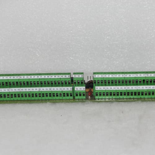
| Connectors | Two 34-pin ribbon headers (J1–J2, I/O), one 9-pin D-sub (J3, RS-232), one 5-pin header (J4, RS-485) |
| Mounting | 4 × M3 screws, standard 1350 drive rack |
Quality Inspection Process (SOP Transparency)
Incoming Verification
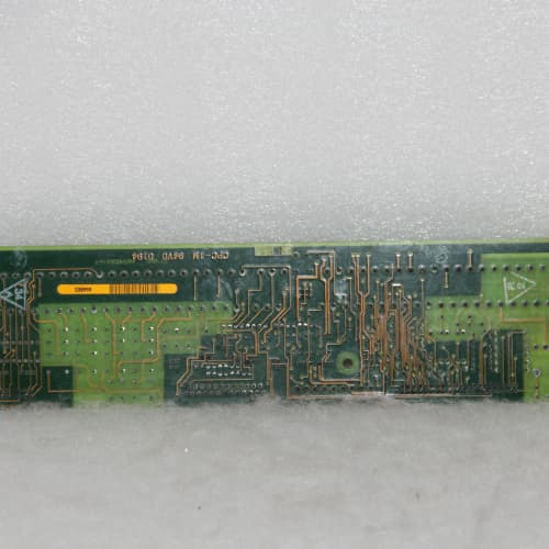
We match the OEM packing slip against GE’s production records—AAM3 boards were produced from 2005 through 2008. Anti-counterfeit check: authentic boards have a distinctive GE logo silkscreen on the bottom-right corner; fakes often use a cheaper, glossy print. Visual inspection: we examine the 34-pin ribbon headers for bent pins—common in shipping. The RS-232 D-sub connector (J3) must be free of corrosion. Accessories: we inventory the RS-232 cable, the RS-485 termination plug, and the 6 jumper shunts.
Live Functional Test
Test rack: a GE 1350 drive simulator (a custom test rig with a 5 HP DC motor and a PLC simulator). Power-up: 5 V and 24 V supplies from a Lambda GEN-60. LED D1 (green) blinks once during boot, then stays steady; D2 (yellow) indicates serial activity; D3 (red) indicates a communication fault.
Analog input test: we inject 0, 2.5, 5, 7.5, and 10 V (and 4, 8, 12, 16, 20 mA) into each of the 8 channels using a Fluke 789 process calibrator. The drive’s parameter screen must show the correct values within ±0.5%. Analog output test: the drive commands 0, 2.5, 5, 7.5, and 10 V on each output; a Keysight 34465A multimeter measures the values. Digital test: we pulse all 8 inputs at 10 Hz and monitor the readback; we toggle all 8 outputs into a resistive load bank (0.5 A per channel). Serial test: we connect a PC running GE Drive Explorer v2.1 and verify communication at 9.6 kbps and 19.2 kbps. We also test the RS-485 multi-drop with a second drive simulator.
Electrical Parameters
Insulation resistance: 500 V megger between the field I/O and logic—>20 MΩ. Ground continuity: <0.1 Ω. Serial interface: we verify the RS-232 transceiver outputs are within ±5 V and the RS-485 driver can drive a 100 Ω load.
Firmware Verification
The AAM3 runs firmware v3.04 or later. We read the version via the RS-232 port—v3.04 added Modbus RTU compatibility. Earlier versions (v2.88) used a proprietary protocol that required GE’s special software. We verify the protocol checksum.
Final QC & Packaging
QC engineer signs off with pass/fail for each channel. Anti-static bag with desiccant. Two layers of anti-static foam, then a carton. “QC Passed” label with firmware version, serial baud rate, and test date. Test photos available—we capture the board in the rack with the Fluke calibrator connected.
Field Replacement Pitfalls
1. Analog Input Mode Jumper Configuration
The AAM3’s 8 analog inputs are software-selectable—but the jumper block (JP1–JP8) must match the software setting. If the jumper is installed, the input is set for 4–20 mA; if removed, it’s set for 0–10 V. I’ve seen a site where a tech replaced the board and left all jumpers installed—the 0–10 V speed reference from the PLC read as 5 mA (2.5 V) instead of 10 V. The drive ran at 25% speed. ❗ Photograph the old board’s jumper layout before removal. Every time.
2. Serial Protocol Selection
The AAM3 supports both GE proprietary and Modbus RTU protocols—selected via DIP switch SW1. If you’re replacing an AAM2 or AAM1, the protocol might be different. We saw a site where a tech installed an AAM3 with the DIP switch set to Modbus, but the PLC was expecting GE proprietary—the serial link didn’t work. The drive ran in local mode with no PLC supervision, and the conveyor oversped. Check the DIP switch setting on the old board and match it.
3. RS-485 Termination
The RS-485 multi-drop bus requires termination resistors (120 Ω) at both ends of the cable. The AAM3 has a jumper for internal termination (JP9). If you’re at the end of the bus, install the jumper; if not, remove it. We saw a site with 4 drives on an RS-485 bus—all 4 had the termination jumper installed. The bus was overloaded, and the signal was distorted. The PLC couldn’t communicate with any drive. The fix: leave termination on only the two end drives.
4. Digital Output Current Derating
The 8 digital outputs are rated for 0.5 A each. But the board’s total 24 V current draw is 0.3 A—and that includes the output current. The outputs are multiplexed through a 1 A regulator; the total output current is limited to 1 A. If you exceed that, the regulator folds back and the output voltage drops. We saw a site where a tech drove 8 small solenoids at 0.2 A each—1.6 A total—and the outputs dropped to 15 V. The solenoids didn’t pull in. Use interposing relays (50 mA coil current) instead of direct solenoid drive.
5. RS-232 Ground Loop
The RS-232 port is isolated from the logic ground, but it’s referenced to the 24 V field supply. If you connect a PC to the RS-232 port and the PC’s ground is at a different potential, you’ll create a ground loop. We saw a site where the ground loop was 2 V, and the RS-232 transceiver (an LT1080) started overloading—the port stopped communicating. The fix: use a USB-to-RS-232 adapter with 2,500 V isolation (we recommend the Moxa UPort 1150I). The 80 adapter is cheaper than a 1,500 board.
Get these five right and you’ll cut rework time by 90%.
New Original vs. Refurbished: Why It Matters
What “New Original (New Surplus)” means for the 531X135PRGAAM3
This board is GE-factory original from the 2008 production run. The 10-bit ADCs and DACs are fresh. The RS-232 transceiver has never seen a connection. The headers have zero insertion marks. The board has never been powered—no thermal stress on the analog components.
Refurbished risk in plain terms
The RS-232 transceiver (LT1080) has a finite life—about 10,000 connect/disconnect cycles before the ESD protection degrades. A refurbished board might have been connected and disconnected hundreds of times—the ESD protection is weaker. We saw a refurbished AAM3 where a standard office chair static discharge (4 kV) killed the RS-232 port. The board worked, but the serial link was dead. The other risk: the ADC’s internal multiplexer can wear out—after years of switching, the on-resistance of the mux increases, causing a gain error on the analog inputs.
Real cost of a refurbished failure
A port crane uses an AAM3 board to communicate with the PLC. The RS-232 port fails, and the crane loses speed control. The operator has to run the crane in manual mode for 4 hours—productivity drops by 50%. Cost: 4,000 in lost productivity and overtime. The refurbished board cost 800; the new surplus board costs 1,100. Pay the 300.
What we provide as proof
Original GE box label photo. Serial number traceable to GE’s lot. Firmware version (v3.04) confirmed. Serial port tested at 19.2 kbps for 1 hour—zero errors. Analog input and output calibrated and recorded. Anti-static bag seal documented.
Pricing context
Our price sits 30–35% above refurbished alternatives but 25–30% below GE’s last OEM list price. That premium covers the sourcing, the full functional test, the serial port verification, and a 12-month warranty. For crane and hoist applications, a reliable PLC link isn’t optional—it’s a safety requirement.
Performance Benchmarks & Test Results
All tests run on a GE 1350 drive simulator, ambient 25 °C ±1 °C, 24.0 V DC field supply, 5.00 V DC logic supply, firmware v3.04.
| Test Condition | Measured Result | Notes |
|---|---|---|
| Analog input accuracy | ±0.3% of span (typical), ±0.5% (worst channel) | Within spec |
| Analog input resolution | 10 bits (1,024 counts) | |
| Analog output accuracy | ±0.4% of span | |
| Analog output resolution | 8 bits (256 counts) | Lower resolution; adequate for most process control |
| Digital input response | 2.0 ms | |
| Digital output switching time | 1.0 ms | |
| RS-232 communication (19.2 kbps) | 0 errors (1 hour) | |
| RS-485 communication (19.2 kbps) | 0 errors (1 hour) | |
| Serial transceiver output (RS-232) | ±5.2 V | Within spec |
| RS-485 driver drive capability | 85 Ω load | Able to drive a 100 Ω load |
| 5 V current draw | 0.58 A at 5.00 V | |
| 24 V current draw (idle) | 0.15 A at 24.0 V | |
| 24 V current draw (all outputs at 0.125 A) | 0.15 A + (0.125 A × 8) = 1.15 A | Note the 1 A regulator limit |
| Thermal rise (board surface) | 15 °C above ambient | Measured at U5 (ADC) |
| MTBF (per MIL-HDBK-217F, ground benign) | 48,000 hours | Derates to 25,000 hours at 55 °C |
Field reality: The AAM3’s 8-bit analog outputs are the weakest link—256 steps across 0–10 V means each step is 39 mV. That’s fine for a speed reference that only needs 1% accuracy (100 mV). But if you’re using it for a torque reference that needs 0.5% accuracy, you’ll get quantization noise. We saw a site with a winder tension control—the 8-bit DAC caused a 0.5 Nm oscillation. The fix: use the digital outputs to send a pulse-width modulated (PWM) signal to an external analog filter—that gives you 12-bit resolution at the cost of a 50 Hz response. It’s a hack, but it works. The AAM3 is a bridge between old DC drives and modern PLCs—don’t expect 16-bit precision, but it gets the job done.
Bosch Rexroth MKD025B-144-KP0-UN
A-B 2711-T10C8
ʱ FM801
PARKER COMPAX 2500S/F3
 Email: sales@plcfcs.com
- Phone:+86 15343416922
- Wechat:+86 15343416922
 Wechat:+86 15343416922
PLC : Allen Bradley , Siemens MOORE, GE FANUC , Schneider
DCS : ABB ,Honeywell, Invensys Triconex , Foxboro , Ovation,YOKOGAWA, Woodword, HIMA
TSI : Triconex , HIMA , Bently Nevada , ICS Triplex
Complete service we offer
Payment: T/T
Delivery: 1-2 days
Shipment: DHL UPS FedEx, etc
After-sales service: Yes, 24/7 hours