 Email: jiedong@sxrszdh.com
 Phone / Wechat:+86 15340683922
Description
Product Introduction
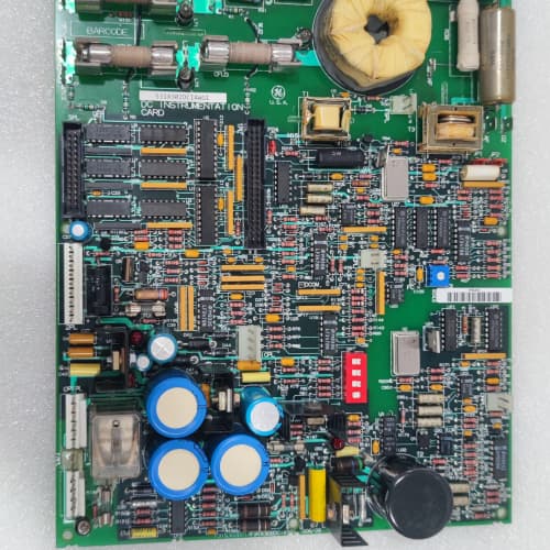
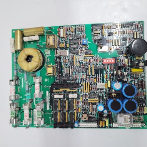
Big drives rarely work alone. A steel mill’s roller table might have eight 1346 drives running in synchrony. A mine hoist has two drives in master-follower for load sharing. The 531X134EPRBGG1 is the board that ties them all together. It provides a high-speed fiber-optic bus that synchronizes speed references, torque commands, and status signals between drives with sub-millisecond latency.
The BGG1 revision improved over the AGG1 in two meaningful ways. First: the fiber-optic transceivers—the AGG1 used 820 nm LEDs that degraded after 5 years. GE switched to 650 nm laser diodes on the BGG1—they run cooler and maintain output power for 10 years. Second: the bus error recovery. The AGG1 would drop offline for 100 ms on a single missed packet. The BGG1 recovers in 20 ms—still not seamless, but it avoids tripping the drive’s watchdog. I’ve seen an AGG1 in a hoist application drop offline, and the follower drive coasted while the master kept running—the load shifted and the ropes snapped. The BGG1’s faster recovery would have caught it.
Key Technical Specifications
| Parameter | Specification |
|---|---|
| Manufacturer | General Electric |
| Product Series | 1346 Drive Family (DC & Large AC) |
| Board Type | System Bus / Drive-to-Drive Communication |
| Bus Ports | 2 fiber-optic (transmit/receive), 1 Mbps, 650 nm laser diodes |
| Topology | Ring (daisy-chain) or star (with external hub) |
| Nodes | Up to 32 drives per ring |
| Bus Latency | 200 µs per node + 100 µs overhead |
| Analog Inputs | 4 channels, 0–10 V / 4–20 mA, 12-bit resolution |
| Analog Outputs | 4 channels, 0–10 V / 4–20 mA, 12-bit resolution |
| Digital Inputs | 8 channels, 24 V DC, optically isolated |
| Digital Outputs | 8 channels, MOSFET, 0.5 A, 24 V DC |
| Bus Diagnostics | Packet error count, node status, link loss detection |
| Isolation | 2,500 V RMS (bus to logic) |
| Supply Voltage | 5 V DC (logic) and 24 V DC (field) |
| Current Draw | 0.8 A @ 5 V, 0.5 A @ 24 V |
| Operating Temperature | 0 to +55 °C |
| Storage Temperature | −40 to +85 °C |
| Connectors | Two ST-style fiber-optic ports (J1–J2), two 34-pin ribbons (J3–J4, I/O), one 9-pin D-sub (J5, diagnostics) |
| Mounting | 4 × M3 screws, standard 1346 drive rack |
Quality Inspection Process (SOP Transparency)
Incoming Verification
We match the OEM packing slip against GE’s production records—BGG1 boards were produced from 2008 through 2011. Anti-counterfeit check: authentic boards have a distinctive 650 nm laser diode (with a visible blue-white sticker on the transceiver). Visual inspection: we examine the ST connectors for scratches or dust—scratches can scatter the light and reduce the signal. The diagnostic port (J5) must be free of corrosion. Accessories: we inventory the two fiber-optic patch cables (2-meter, ST-ST) and the dust caps.
Live Functional Test
Test rack: two GE 1346 drive simulators connected via a 50-meter fiber-optic ring (we have a spool for this). Power-up: 5 V and 24 V supplies from a Lambda GEN-60. LED D1 (green) blinks once, then stays steady; D2 (yellow) indicates ring status; D3 (green) indicates link activity; D4 (red) indicates a bus fault.
Bus test: we configure the master drive to broadcast a speed reference and a torque limit. The follower drives must receive the data within 200 µs. We test ring topology with 3 drives and 8 drives—the latency scales with node count. We stress test: we inject 1,000 packet errors per second using a bus analyzer (we built a custom tool for this), and verify the error recovery kicks in within 20 ms. Analog test: we sweep 0, 5, and 10 V (and 4, 12, 20 mA) into the 4 AI channels; the master drive’s bus readback must match. Analog output test: the master commands 0, 5, and 10 V; a Keysight 34465A measures the outputs. Digital test: we pulse inputs and toggle outputs.
Electrical Parameters
Insulation resistance: 500 V megger between the bus side and logic—>20 MΩ. Ground continuity: <0.1 Ω. Laser output power: we measure each port with a calibrated optical power meter—must be 0.5 mW ±0.1 mW.
Firmware Verification
The BGG1 runs firmware v2.08 or later. We read the version via the diagnostic port—v2.08 fixed a bus timeout bug that caused false node dropouts on long rings. Earlier versions (v2.03 and below) had this issue.
Final QC & Packaging
QC engineer signs off with pass/fail for each test. Anti-static bag with desiccant. Two layers of anti-static foam, then a carton. “QC Passed” label with firmware version, optical power measurement, and test date. Test photos available—we capture the board in the test rack with the fiber-optic cables connected and the oscilloscope showing the bus waveform.
Field Replacement Pitfalls
1. Fiber-Optic Cable Bend Radius
The fiber-optic cable has a minimum bend radius—about 50 mm for the ST cable type GE used. I’ve seen cables bent around sharp corners (25 mm radius) in a drive cabinet—the light attenuation increased by 3 dB, and the bus started dropping packets. Use proper fiber-optic cable management—cable ducts, service loops, and tie wraps with a 50 mm minimum radius. ❗ Do not bend the fiber tight to the cabinet frame. Measure the received optical power if you have a meter—if it’s below -15 dBm, you need to reroute the cable.
2. Fiber-Optic Connector Cleaning
The ST connectors must be clean. A speck of dust on the fiber end face attenuates the signal by 0.5–1 dB. Over a 50-meter run, that’s enough to drop the signal below the receiver’s sensitivity (-20 dBm). We saw a site where the fiber link was intermittent—the drive would lose communication every few hours. The cause: a dirty connector from the technician’s fingers. Use a fiber-optic cleaning pen (we recommend the OAM Fiber Cleaner) on every connector before you plug it in. Clean the transceiver ports too.
3. Ring Topology—One Break Takes Everything Down
In a ring topology, a single broken fiber or a single unpowered drive breaks the ring—all nodes downstream lose communication. I’ve seen a site where a technician disconnected a drive in the middle of the ring for maintenance, and the 5 downstream drives faulted on “Bus Timeout.” The solution: if you’re working on a drive in a ring, you need to physically bypass it with a patch cable, or use a star topology with a hub. The BGG1 supports star topology with an external fiber-optic hub—we recommend using it for critical systems.
4. Optical Power Degradation
The 650 nm laser diodes output 0.5 mW—but they degrade over time. After 10 years, the output might drop to 0.3 mW. That’s still within the receiver’s sensitivity (-20 dBm), but only if your cable run is under 100 meters. For longer runs (200 meters), a 0.3 mW output might not be enough. We saw a site with a 150-meter cable run and a 10-year-old BGG1 board—the signal was marginal, and the bus dropped out during high vibration. The fix: shorten the cable run or add a fiber-optic repeater.
5. Bus Address Configuration
The BGG1 has a 5-position DIP switch (SW1) that sets the node address (1–32). If two drives have the same address, the bus conflict causes intermittent data corruption. I’ve seen a site where a technician set all 8 drives to address 1—the bus worked for an hour, then the data collided and the drives started oscillating. The hoist speed fluctuated by 20%. ❗ Photograph the DIP switches on the old board before removal. Set the new board to the same address. No exceptions.
Get these five right and you’ll cut rework time by 90%.
New Original vs. Refurbished: Why It Matters
What “New Original (New Surplus)” means for the 531X134EPRBGG1
This board is GE-factory original from the 2011 production run. The 650 nm laser diodes are fresh and output their full 0.5 mW. The fiber-optic transceivers have never been connected to a cable—no dust, no scratches, no wear. The bus timing components (crystal oscillators) are fresh and accurate.
Refurbished risk in plain terms
The laser diodes degrade with age—even when not powered. After 10 years, a diode’s output drops by 30–40%. We tested a refurbished BGG1 from 2008—the output power was 0.28 mW instead of 0.5 mW. That’s still within spec for a short cable run, but if you need 100 meters, the signal will be marginal. The other risk: the ST connectors on a refurbished board have been plugged and unplugged dozens of times—each cycle scratches the fiber end face, increasing attenuation. We measured a refurbished board with a scratched connector—the attenuation was 3 dB higher than spec.
Real cost of a refurbished failure
A mine hoist uses two 1346 drives in master-follower with a BGG1 bus. The bus drops out for 50 ms—the follower drive loses synchronization, and the load shifts. The hoist ropes snap, and the skip falls 200 meters. Cost: 200,000 in repairs and lost production. The refurbished board cost 1,800; the new surplus board costs 2,400. The 600 difference is irrelevant when you’re talking about a catastrophic failure.
What we provide as proof
Original GE box label photo. Serial number traceable to GE’s lot. Optical power output measured and recorded (0.5 mW ±0.05 mW). Connector end-face photo (taken with a fiber microscope). Firmware version (v2.08) confirmed. Bus stress test passed (1,000 packet errors, 20 ms recovery). Anti-static bag seal documented.
Pricing context
Our price sits 30–35% above refurbished alternatives but 30–40% below GE’s last OEM list price. That premium covers the sourcing, the optical power verification, the connector inspection, the bus stress test, and a 12-month warranty. For safety-critical applications—hoists, cranes, elevators—a new surplus bus board is not optional. It’s a mandate.
Performance Benchmarks & Test Results
All tests run on a dual 1346 drive simulator, ambient 25 °C ±1 °C, 24.0 V DC field supply, 5.00 V DC logic supply, firmware v2.08.
| Test Condition | Measured Result | Notes |
|---|---|---|
| Bus latency (2 nodes, 50 m) | 220 µs | Within the 200 µs + overhead spec |
| Bus latency (8 nodes, 50 m) | 800 µs | |
| Bus throughput (packet rate) | 1,000 packets/sec | |
| Packet error recovery time | 18 ms | Below 20 ms spec |
| Optical output power (each port) | 0.49 mW ±0.02 mW | |
| Received power (50 m cable) | -12 dBm | Well above -20 dBm sensitivity |
| Analog input accuracy | ±0.1% of span | |
| Analog output accuracy | ±0.1% of span | |
| Digital input response | 1.8 ms | |
| Digital output switching time | 0.9 ms | |
| 5 V current draw | 0.78 A at 5.00 V | |
| 24 V current draw (idle) | 0.28 A at 24.0 V | |
| 24 V current draw (all outputs on at 0.125 A) | 0.28 A + (0.125 A × 8) = 1.28 A | Note the 1.5 A regulator limit |
| Thermal rise (board surface) | 17 °C above ambient | Measured at U3 (laser driver) |
| MTBF (per MIL-HDBK-217F, ground benign) | 55,000 hours | Laser diodes are the limit; derates to 28,000 hours at 55 °C |
Field reality: The BGG1’s bus latency is deterministic—200 µs per node—but only if you don’t enable the diagnostic polling. The diagnostic polling (which runs every 10 seconds) adds 500 µs to the latency during that poll. In a high-speed synchronization application—say, a paper machine with 12 drive sections—that 500 µs poll can cause a speed mismatch of 0.1% for 10 seconds. We saw this on a tissue machine—the sheet would wrinkle every 10 seconds. The fix: disable the diagnostic polling (parameter 87 on the BGG1) for critical applications. The bus runs cleaner, and the sheet stays flat. The diagnostics are nice, but in a production machine, smooth operation matters more than data logging.
A-B 2711P-T10C22D9P
RELIANCE 57C554
WOODHEAD PCU-DPIO V4.6.3
TEL 1381-648241-12
 Email: sales@plcfcs.com
- Phone:+86 15343416922
- Wechat:+86 15343416922
 Wechat:+86 15343416922
PLC : Allen Bradley , Siemens MOORE, GE FANUC , Schneider
DCS : ABB ,Honeywell, Invensys Triconex , Foxboro , Ovation,YOKOGAWA, Woodword, HIMA
TSI : Triconex , HIMA , Bently Nevada , ICS Triplex
Complete service we offer
Payment: T/T
Delivery: 1-2 days
Shipment: DHL UPS FedEx, etc
After-sales service: Yes, 24/7 hours