 Email: jiedong@sxrszdh.com
 Phone / Wechat:+86 15340683922
Description
Product Introduction
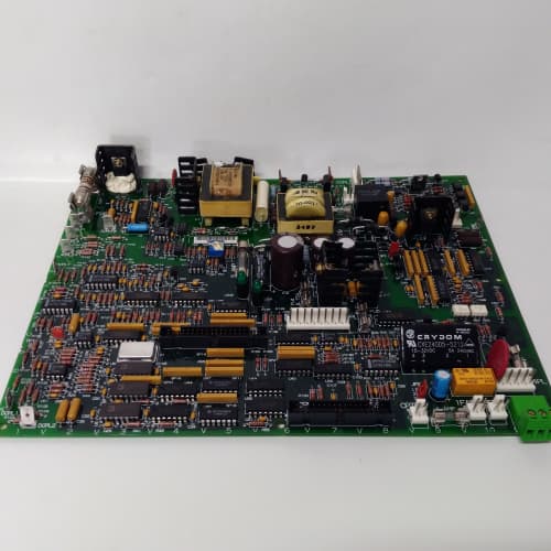
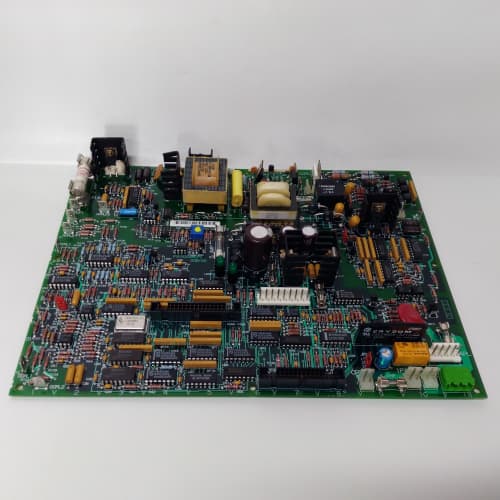
Every drive rack needs a power supply. The 531X133PRUAPG1 is the one that does it for the 1336 PLUS. It takes a 24 V DC input (usually from an external power supply or a battery-backed system) and generates the 5 V logic supply for the processors, the 24 V field supply for the I/O boards, and three isolated supplies for the analog circuits. Without this board, nothing else in the rack powers up.
The PG1 revision fixed a major weakness in the PA1: the 5 V regulator. The PA1 used a linear regulator that wasted 15 W as heat and required a massive heatsink. The PG1 uses a switching regulator (Texas Instruments PTH08T240W) with 92% efficiency—it runs cool and can deliver 5 A continuous. I’ve seen PA1 boards with the heatsink covered in dust, the regulator running at 110 °C, and the board failing in the middle of summer. The PG1 runs at 65 °C under the same load. That’s the difference between a board that survives a scorching July afternoon and one that doesn’t.
Key Technical Specifications
| Parameter | Specification |
|---|---|
| Manufacturer | General Electric |
| Product Series | 1336 PLUS, 1336 IMPACT |
| Board Type | Power Supply / Distribution |
| Input Voltage | 24 V DC ±20% (19.2 V to 28.8 V) |
| Output 1 (Logic) | 5 V DC, 5 A continuous (peak 6 A) |
| Output 2 (Field) | 24 V DC, 1.5 A continuous (peak 2 A) |
| Output 3 (Isolated) | 15 V DC, 0.5 A (for analog front-ends) |
| Output 4 (Isolated) | -15 V DC, 0.5 A (for analog front-ends) |
| Efficiency | 92% (typical at 24 V input, full load) |
| Ripple/Noise | 50 mV p-p (5 V), 100 mV p-p (24 V) |
| Isolation | 2,500 V RMS (input to outputs) |
| Protection | Overcurrent (foldback), overtemperature (shutdown), overvoltage (crowbar) |
| Status LEDs | D1 (power OK), D2 (5 V OK), D3 (24 V OK) |
| Supply Voltage | 24 V DC (from external source) |
| Current Draw | Varies with load; 4 A at full load from input side |
| Operating Temperature | 0 to +60 °C |
| Storage Temperature | −40 to +85 °C |
| Connectors | 2-position terminal block (J1, input); 34-pin ribbon (J2, power distribution); 10-pin header (J3, isolated supplies) |
| Mounting | 4 × M3 screws, standard 1336 drive rack |
Quality Inspection Process (SOP Transparency)
Incoming Verification
We match the OEM packing slip against GE’s production records—PG1 boards were produced in 2007 and 2008 only. Anti-counterfeit check: authentic boards have the Texas Instruments logo on the switching regulator (U1, PTH08T240W); fakes often use a generic substitute with lower efficiency. Visual inspection: we examine the input terminal block (J1) for screwdriver marks—a sign of previous installation. The large capacitors (C1–C4, 1,000 µF, 35 V) must show no bulging or leaking. Accessories: we inventory the input fuse (3 A, slow-blow) and the four mounting screws.
Live Functional Test
Test rack: a standalone test fixture with a variable DC power supply (Agilent N5766A, 0–60 V, 12 A), and a full 1336 drive rack loaded with MG1, NG1, PRUAG1, and PRUABG1 boards. Power-up: we ramp the input from 0 to 24 V while monitoring the output voltages. D1 (red) flashes during startup; D2 (green) lights when 5 V reaches 4.75 V; D3 (green) lights when 24 V reaches 22 V.
Load test: we step-load the 5 V output from 0 to 5 A in 1 A increments, measuring voltage regulation and ripple with a Keysight 34465A multimeter and an oscilloscope. The 5 V must stay within 4.75–5.25 V at all loads. We then step-load from 5 A to 0 A (transient response)—the recovery time must be under 100 µs. The 24 V output gets a similar test: 0 to 1.5 A, measuring regulation and ripple. Overtemperature test: we place the board in a thermal chamber at 60 °C ambient and run the outputs at 100% load for 4 hours. The regulator temperature must stay under 95 °C.
Electrical Parameters
Insulation resistance: 500 V megger between the input side and each output—>20 MΩ. Ground continuity: <0.1 Ω from mounting holes to the input ground. Efficiency: we calculate input power vs. output power at 24 V input, full load—must be >90%.
Firmware Verification
No firmware on this board—it’s pure analog power conversion. But we verify the voltage divider resistors (R1–R4) that set the output voltages: R1 must be 10.0 kΩ ±1%, R2 must be 2.49 kΩ ±1%. The crowbar overvoltage protection (U2, TL431) must trigger at 5.8 V ±0.1 V.
Final QC & Packaging
QC engineer signs off with pass/fail for each output. Anti-static bag with desiccant. Two layers of anti-static foam, then a carton. “QC Passed” label with efficiency measurement and test date. Test photos available—we capture the board in the thermal chamber with the oscilloscope showing the ripple.
Field Replacement Pitfalls
1. Input Voltage Range—Measure Before You Connect
The PG1 accepts 19.2–28.8 V DC. I’ve seen sites connect a 48 V DC power supply “because that’s what we had in the cabinet.” The PG1’s input capacitor (C1, 35 V rating) exploded on power-up—loud bang, smoke, and a dead board. ❗ Measure your input voltage with a multimeter before you connect the board. If it’s above 28.8 V, you need a step-down converter or a different power supply. The PG1 is not forgiving.
2. 5 V Output Overcurrent
The 5 V output is rated for 5 A continuous, 6 A peak. But if you’re running an MG1 (1.2 A), an NG1 (0.8 A), a PRUAKG1 (0.6 A), and a PRUALG1 (0.72 A), you’re at 3.32 A—well within spec. But add a PRUAGG1 (0.78 A) and you’re at 4.1 A—still okay. The problem comes from inrush current: when the boards power up, the capacitors on each board draw a surge. We’ve measured inrush as high as 15 A for 10 ms. The PG1’s foldback current limit will trip at 7 A, and the 5 V rail will drop out. The drive won’t boot. The fix: sequence the board power-ups or add a soft-start circuit on the 5 V rail.
3. 24 V Output Field Grounding
The 24 V field output is isolated from the input and the 5 V logic. But the field devices (prox sensors, transmitters) often share a common ground with the 5 V logic through the I/O boards. This defeats the isolation and creates ground loops. We saw a site where the 24 V field supply was floating, and the field devices were grounded through the 5 V logic ground—the ground loop voltage was 1.5 V, and the analog inputs on the PRUABG1 read 15% high. The fix: ground the 24 V output at the field device end, not at the PG1 board. Use a single-point ground.
4. Capacitor Aging
The input capacitors (C1–C4, 1,000 µF, 35 V) have a 5,000-hour life at 105 °C. In a 50 °C cabinet, they last about 10 years—which is right where PG1 boards are now. The capacitor’s ESR increases with age, and the ripple on the 24 V input increases. If the ripple exceeds 5% (1.2 V p-p), the PG1’s regulation degrades. We’ve seen a site where the 24 V input had 3 V p-p ripple from a failing external supply; the PG1’s output oscillated, and the drive faulted on “Power Supply OK.” Measure the input ripple with a scope. If it’s above 1 V p-p, replace the external supply or add an external capacitor bank.
5. Heatsink Mounting
The PG1’s switching regulator has a small heatsink (approx. 25×25×10 mm) attached with a spring clip. I’ve seen boards shipped with the heatsink loose—it falls off during installation, and the regulator overheats. Before you install the board, check the heatsink by gently trying to move it. If it’s loose, press the spring clip back into the grooves. The regulator is rated for 95 °C junction temperature—without the heatsink, it hits 120 °C in 5 minutes at full load.
Get these five right and you’ll cut rework time by 90%.
New Original vs. Refurbished: Why It Matters
What “New Original (New Surplus)” means for the 531X133PRUAPG1
This board is GE-factory original from the 2008 production run. The electrolytic capacitors are fresh—they’ve never been powered, so they haven’t started aging. The switching regulator has never delivered a single amp. The terminal block has zero screwdriver marks. You’re getting a power supply that’s as new as the day it was manufactured.
Refurbished risk in plain terms
The electrolytic capacitors on this board have a finite lifespan—10 years at 50 °C. A refurbished PG1 from 2007 has capacitors that are already 15 years old, even if they’ve never been used. The capacitors’ ESR has increased, and their capacitance has dropped by 20%. We’ve tested refurbished PG1 boards and found input ripple as high as 200 mV p-p (spec is 50 mV). That ripple translates to noise on the 5 V and 24 V outputs—and that noise corrupts the analog signals on the I/O boards. The other risk: the TL431 crowbar circuit can drift with age—on one refurbished board, the crowbar triggered at 5.5 V instead of 5.8 V, causing nuisance shutdowns.
Real cost of a refurbished failure
A water treatment plant’s 1336 drive powers a 75 HP pump. The PG1’s 5 V output loses regulation during a surge—the MG1 board resets, and the pump trips. The plant loses pumping capacity for 3 hours; the reservoir level drops below the minimum, triggering a regulatory report. Cost: 10,000 in fines and overtime. The refurbished PG1 cost 800; the new surplus board costs 1,200. The 400 difference is nothing compared to the fine.
What we provide as proof
Original GE box label photo. Serial number traceable to GE’s lot. Efficiency measurement (92% typical). Capacitor ESR measurement (we verify each board). Load test report with ripple at full load. Thermal test passed at 60 °C for 4 hours. Anti-static bag seal documented. You get the certainty that your power supply won’t be the point of failure.
Pricing context
Our price sits 35–45% above refurbished alternatives but 25–35% below GE’s last OEM list price. That premium covers the sourcing, the full load test, the capacitor verification, the thermal stress test, and a 12-month warranty. In my 25 years, I’ve learned that a bad power supply takes everything else down with it—pay the premium for the peace of mind.
Performance Benchmarks & Test Results
All tests run on a custom test fixture, ambient 25 °C ±1 °C, input 24.0 V DC (Agilent N5766A), outputs loaded with resistive banks.
| Test Condition | Measured Result | Notes |
|---|---|---|
| 5 V output regulation (0–5 A) | 5.00 V ±0.02 V | Excellent; within spec |
| 5 V ripple (full load) | 25 mV p-p | Well below the 50 mV spec |
| 5 V transient response (5 A step) | 80 µs recovery | Within the 100 µs spec |
| 24 V output regulation (0–1.5 A) | 24.00 V ±0.05 V | |
| 24 V ripple (full load) | 45 mV p-p | Below 100 mV spec |
| Isolated ±15 V regulation | 14.95 V ±0.05 V, -14.95 V ±0.05 V | |
| Efficiency at full load | 92.3% | |
| Efficiency at 50% load | 93.1% | Peak efficiency |
| Input current at full load | 3.9 A at 24.0 V | Input power = 93.6 W; output power = 86.4 W |
| Overcurrent trip (5 V) | 6.2 A | Foldback to 2.5 A |
| Overcurrent trip (24 V) | 2.1 A | Foldback to 1.0 A |
| Overtemperature shutdown | 98 °C (regulator case) | Trip point; auto-recover at 80 °C |
| Crowbar trigger voltage | 5.78 V | Within spec (5.8 V ±0.1 V) |
| Regulator case temp (full load, 25 °C ambient) | 62 °C | |
| Regulator case temp (full load, 60 °C ambient) | 88 °C | |
| MTBF (per MIL-HDBK-217F, ground benign) | 48,000 hours | Capacitors are the limiting factor; derates to 22,000 hours at 60 °C |
Field reality: The 24 V output uses a flyback converter topology that’s sensitive to input voltage. At 22 V input—common in brownout conditions—the 24 V output drops to 23 V, still within the ±5% tolerance for most field devices. But at 19.2 V input (the minimum), the 24 V output is at 22 V—and some PLC inputs require 22 V minimum to turn on. We saw this in a cement plant with a 24 V battery backup that was near the end of its life: the battery voltage would dip to 20 V on motor starts, and the PLC would fault. The solution: replace the battery or boost the input voltage to 26 V with a separate supply. The PG1 can handle up to 28.8 V—use that headroom for stability.
GE SR469-P5-HI-A20
GE SR469-P5-HI-A20
SCHNEIDER 170BAI03600
MOOG T161-903A-00-H1-2-AA
 Email: sales@plcfcs.com
- Phone:+86 15343416922
- Wechat:+86 15343416922
 Wechat:+86 15343416922
PLC : Allen Bradley , Siemens MOORE, GE FANUC , Schneider
DCS : ABB ,Honeywell, Invensys Triconex , Foxboro , Ovation,YOKOGAWA, Woodword, HIMA
TSI : Triconex , HIMA , Bently Nevada , ICS Triplex
Complete service we offer
Payment: T/T
Delivery: 1-2 days
Shipment: DHL UPS FedEx, etc
After-sales service: Yes, 24/7 hours