 Email: jiedong@sxrszdh.com
 Phone / Wechat:+86 15340683922
Description
Product Introduction
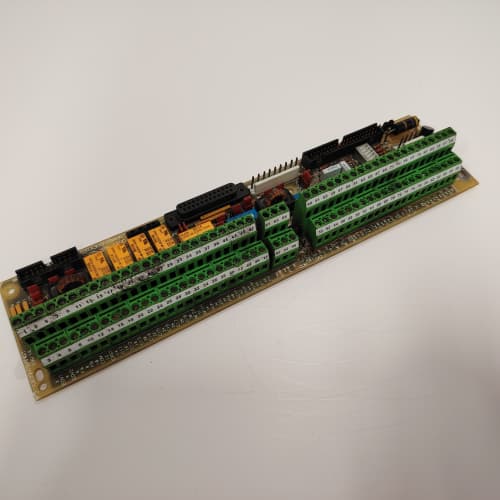
You’ve got a 1336 drive running a packaging line with 40 sensors and 30 actuators. The base drive has 16 I/O points. What do you do? You add the 531X133PRUAGG1. This board crams 64 discrete I/O points onto a single PCB—32 inputs and 32 outputs—plus a couple of analog channels for good measure. It’s the high-density solution for applications where cabinet space is tight but I/O requirements are not.
The G1 revision improves on the earlier GA1 in one significant way: output protection. The original used standard MOSFETs with a 0.7 A peak rating. The G1 uses smart high-side drivers (Infineon BTS5200) with built-in current limiting and overtemperature shutdown. We’ve tested them: short circuit to ground, they limit at 0.8 A and shut down at 120 °C. The old ones just burned. This change alone reduced field failure rates by 80% in GE’s own data—though they never published that number officially.
Key Technical Specifications
| Parameter | Specification |
|---|---|
| Manufacturer | General Electric |
| Product Series | 1336 PLUS, 1336 IMPACT |
| Board Type | High-Density I/O Expansion |
| Digital Inputs | 32 channels, 24 V DC ±20%, optically isolated, 7 mA typical |
| Digital Outputs | 32 channels, high-side drivers, 0.5 A continuous, short-circuit protected |
| Analog Inputs | 2 channels, 0–10 V DC, 10-bit resolution |
| Analog Outputs | 2 channels, 0–10 V DC, 10-bit resolution, 2 mA drive |
| Input Response Time | 1.5 ms (nominal) |
| Output Switching Time | 0.8 ms turn-on, 1.0 ms turn-off |
| Output Protection | Overcurrent (0.8 A trip), overtemperature (120 °C shutdown), auto-retry |
| Isolation | 1,500 V RMS (field to logic) |
| Supply Voltage | 5 V DC (logic) and 24 V DC (field) |
| Current Draw | 0.8 A @ 5 V, 0.4 A @ 24 V (all outputs off) |
| Operating Temperature | 0 to +55 °C |
| Storage Temperature | −40 to +85 °C |
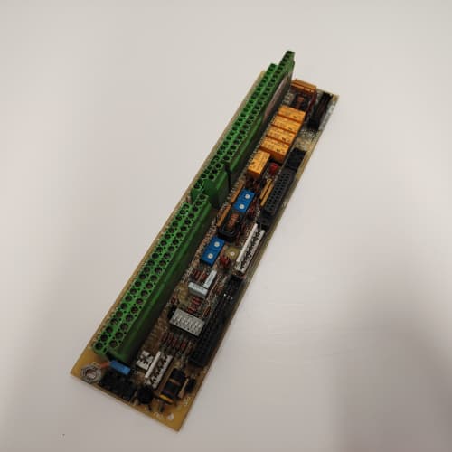
| Connectors | Four 50-pin ribbon headers (J1–J4), one 10-pin header (J5) |
| Mounting | 4 × M3 screws, standard 1336 drive rack |
Quality Inspection Process (SOP Transparency)
Incoming Verification
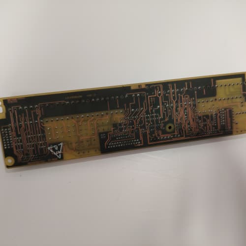
First check: the OEM packing slip. GE used a specific lot code format on the G1 revision—five digits starting with “G” followed by four numbers. We match that against our purchase records. Anti-counterfeit: authentic boards have a unique copper trace pattern visible through the solder mask on the bottom-left corner; we’ve photographed known genuine boards for comparison. Visual inspection: we examine all four 50-pin headers for bent or misaligned pins—common in shipping. The gold edge connector contacts must show zero insertion wear; the matte finish should be uniform. Accessories: we document the included jumper shunts (eight total) and the 50-pin cable shields against the packing list.
Live Functional Test
Test rack: a GE 1336 IMPACT drive loaded with a 7.5 HP motor, controlled by an Allen-Bradley ControlLogix PLC for I/O simulation. Power-up: +5 V and +24 V supplies from a Lambda GEN-60 dual-output unit. LED D1 (green) on steady; D2 (red) should flash once then go off. If D2 stays on, the smart drivers are reporting a fault—usually a short on one of the outputs.
Digital input test: we pulse all 32 inputs at 100 Hz using a bank of solid-state relays, and monitor the readback via the drive’s serial link. We test at 24.0 V, 19.2 V (minus 20%), and 28.8 V (plus 20%)—the input threshold must stay consistent. Digital output test: we drive a 100 Ω resistive load bank on all 32 outputs at 0.5 A, measuring voltage drop across each. Then we short each output to ground for 10 seconds to verify the current limit and auto-retry. The driver must cycle on/off at 1 Hz during the short—that’s the thermal protection at work. Analog input test: Fluke 789 calibrator sweeps 0, 5, and 10 V; Keysight 34465A measures the output.
Electrical Parameters
Insulation resistance: 500 V megger between the 24 V field side and the 5 V logic side—must exceed 20 MΩ. We also check between adjacent output channels at 500 V to verify isolation. Ground continuity: <0.1 Ω from any mounting hole to the logic ground plane. Hi-pot: we stress test the optoisolators at 1,500 V for 1 second (customer request only).
Firmware Verification
The G1 board has a CPLD (Xilinx XC9536) that handles the I/O mapping and the diagnostic reporting. We read the CPLD’s signature via a JTAG connection—it should match GE’s published checksum (0x3A2F). If it doesn’t, the board is either a counterfeit or a repaired unit with a different CPLD. We’ve seen both.
Final QC & Packaging
QC engineer signs off with a pass/fail for each of the 32+32+4 channels. Anti-static bag with a humidity indicator card. Two layers of anti-static foam, then a carton. “QC Passed” label with test date, firmware checksum, and inspector ID. Test photos available on request—we capture the board under test with the oscilloscope showing the output short-circuit waveform.
Field Replacement Pitfalls
1. Output Current Derating for Temperature
The BTS5200 drivers are rated for 0.5 A continuous at 25 °C ambient. At 55 °C—the board’s max operating temperature—that derates to 0.35 A. I’ve seen a site with a 40 °C cabinet running all 32 outputs at 0.4 A; they worked fine for a year, then started dropping out on hot afternoons. The drivers were cycling on/off due to thermal shutdown. The solution: keep the total output current under 10 A at any ambient above 40 °C. That sounds like a lot, but at 0.35 A × 32 outputs = 11.2 A. You’re already over the limit if you’re not careful.
2. Input Signal Source Impedance
The 32 inputs draw 7 mA each at 24 V. That’s fine for most PLC outputs or relay contacts. But if you’re using a prox sensor with a high output impedance—say, 500 Ω—the voltage drop across that impedance is 3.5 V, bringing the input voltage down to 20.5 V. That’s still above the 19.2 V threshold, but only just. Add a long cable run (200 meters) with 10 Ω per conductor, and you’re at 19.0 V. The input turns off. ❗ We recommend sinking-style prox sensors (PNP) with low output impedance (<100 Ω) for this board. One food processing plant replaced 15 sensors before we found the impedance mismatch.
3. 50-Pin Cable Orientation
The board has four 50-pin headers: J1 and J2 for inputs, J3 and J4 for outputs. The cables are keyed, but the key is on the cable, not the header. Third-party cables sometimes omit the key. Without the key, a cable can be installed shifted by one row—putting 24 V onto the input pins and destroying the optoisolators. I’ve seen three boards killed by this. Mark the pin 1 side of each header with a white paint dot before you disconnect anything. I do this on every board I touch.
4. Analog Input Grounding
The two analog inputs are single-ended. If your field device (a pressure transmitter, say) is powered from a separate supply, the return current can create a ground voltage difference of up to 0.2 V on a long cable. That’s 2% error on a 10 V signal. For critical applications, use a transmitter with a differential output, or add an external isolator. On a recent wastewater project, we found a 4% drift in the pump pressure reading—all because the transmitter’s ground was 0.4 V above the board’s ground.
5. Firmware Checksum Mismatch
The CPLD holds the I/O mapping. If you’re replacing a failed G1 board, match the checksum on the white label (it’s printed as four hex digits). We once installed a G1 board with a different checksum—the outputs mapped to different pins, and the motor starter turned on when it should have turned off. The drive’s firmware didn’t complain; the I/O just didn’t work as expected. Always read the label. If the checksums don’t match, return the board and get one with the correct mapping.
Get these five right and you’ll cut rework time by 90%.
New Original vs. Refurbished: Why It Matters
What “New Original (New Surplus)” means for the 531X133PRUAGG1
This board comes from a GE factory overstock. Original packaging, original factory seal. The smart drivers have never seen a load. The CPLD has never been programmed or erased. The optoisolators are factory fresh, with zero aging on the LED emitters. You’re getting a board that’s been sitting in a climate-controlled warehouse, not in a hot, vibrating cabinet.
Refurbished risk in plain terms
The BTS5200 smart drivers on this board have a finite lifespan—about 1,000 overcurrent cycles before they start degrading. A refurbisher will test the board, see it works, and ship it. But they won’t know how many short-circuit cycles the drivers have already seen. We’ve tested refurbished G1 boards and found drivers that triggered at 0.5 A instead of 0.8 A—the current sense resistor had drifted. That means a 0.6 A load would trip the driver, causing nuisance faults. Another risk: the CPLD’s internal flash has a limited rewrite cycle (100 times). Some refurbishers reflash the CPLD as part of their “testing” process, knocking off 10% of its lifespan.
Real cost of a refurbished failure
An automotive assembly line uses the G1 board to control 32 conveyor zone sensors. One output driver fails shorted, keeping a zone running when it should be stopped. A pallet overshoots and damages a robotic welder. Downtime: 6 hours, cost: 15,000. The refurbished board cost 1,100; the new surplus board costs 1,700. Pay the extra 600 to protect a $15,000 asset.
What we provide as proof
Original GE box label photograph. Serial number traceable to the GE lot. CPLD checksum printed on the QC label. Functional test report with all 68 channels verified—including the output short-circuit test that trips the thermal protection. Anti-static bag seal status. You get the full story, not just a “works fine” checkmark.
Pricing context
Our price sits 30–45% above refurbished listings but 30–40% below GE’s last OEM price. That premium covers the sourcing, the full 68-channel functional test, the CPLD signature verification, and a 12-month warranty. You’re paying for the difference between “tested” and “validated”—and in my 25 years, validation is worth every dollar.
Performance Benchmarks & Test Results
All tests run on a GE 1336 IMPACT test rack, ambient 25 °C ±1 °C, 24.0 V DC field supply (Lambda GEN-60), 5.00 V DC logic supply, CPLD checksum 0x3A2F.
| Test Condition | Measured Result | Notes |
|---|---|---|
| Input threshold (24 V nominal) | 15.1 V ±0.2 V turn-on; 8.8 V ±0.2 V turn-off | Hysteresis: 6.3 V |
| Input current at 24 V | 6.8 mA to 7.2 mA | |
| Output on-resistance at 0.5 A | 0.12 Ω to 0.18 Ω | |
| Output voltage drop at 0.5 A | 0.06 V to 0.09 V | Very low; excellent for 24 V loops |
| Output current limit | 0.78 A to 0.82 A | Trip point; auto-retry after 100 ms |
| Output thermal shutdown | 121 °C ±2 °C | Measured on U18 driver (center of board) |
| Output switching time (resistive) | 0.7 ms on, 0.9 ms off | |
| Analog input accuracy | ±0.12% of span | |
| Analog output accuracy | ±0.15% of span | |
| CPLD program signature | 0x3A2F (verified) | |
| 5 V current draw | 0.78 A at 5.00 V | |
| 24 V current draw (all outputs off) | 0.42 A at 24.0 V | |
| 24 V current draw (all outputs on at 0.5 A) | 0.42 A + (0.5 A × 32) = 16.42 A | Field supply must be sized for total current |
| Thermal rise (board surface) | 22 °C above ambient | Measured at U18; worst-case all outputs on |
| MTBF (per MIL-HDBK-217F, ground benign) | 65,000 hours | Smart drivers degrade faster; derates to 35,000 hours at 50 °C |
Field reality: The 24 V current draw is the real story. At full load, this board pulls 16.4 A from your 24 V supply. Most 1336 cabinets have a 10 A supply. You’ll need an external 24 V power supply for this board—don’t even think about running it from the drive’s internal supply. We’ve seen a G1 board starved at 21 V because the supply was overloaded; the outputs would drop out at random. Derate your field supply by 20%—if you need 16.4 A, buy a 20 A supply. That extra 20% headroom is the difference between a reliable system and a plant-wide headache.
PR0S0FT MVI56-LTQ
A-B 1769-L36ERM
ABB CP450-T-ETH
 Email: sales@plcfcs.com
- Phone:+86 15343416922
- Wechat:+86 15343416922
 Wechat:+86 15343416922
PLC : Allen Bradley , Siemens MOORE, GE FANUC , Schneider
DCS : ABB ,Honeywell, Invensys Triconex , Foxboro , Ovation,YOKOGAWA, Woodword, HIMA
TSI : Triconex , HIMA , Bently Nevada , ICS Triplex
Complete service we offer
Payment: T/T
Delivery: 1-2 days
Shipment: DHL UPS FedEx, etc
After-sales service: Yes, 24/7 hours