 Email: jiedong@sxrszdh.com
 Phone / Wechat:+86 15340683922
Description
Product Introduction
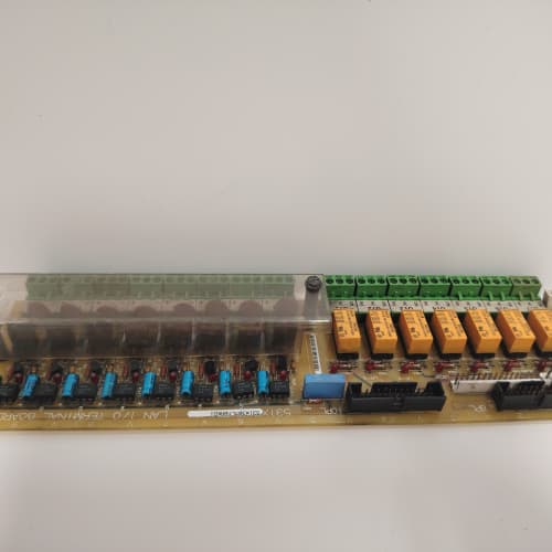
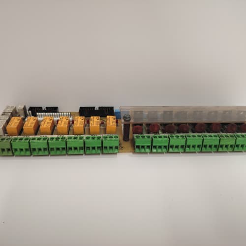
The 531X133PRUAAG1 is the translator between your PLC cabinet and a GE 1336 series drive. This board takes the 24 V DC discrete signals from a controller — say, an Allen‑Bradley SLC‑500 or a Modicon Quantum — and conditions them for the drive’s internal logic levels. On the flip side, it returns status bits back to the PLC. It’s a dumb board in the best sense: no processor, no firmware to corrupt, just signal conditioning and optoisolation.
What sets this PRUAAG1 apart from the older PRUAAB1? The output stages. The earlier version used Darlington transistors that dropped 1.2 V at 0.5 A. This revision uses MOSFETs with an on‑resistance of 0.3 Ω — you get a true 24 V swing even under full load. The analog outputs also gained a 10‑bit resolution DAC, compared to the previous 8‑bit part. That means smoother speed ramps if you’re feeding an analog speed reference back to the PLC.
Key Technical Specifications
| Parameter | Specification |
|---|---|
| Manufacturer | General Electric |
| Product Series | 1336 PLUS, 1336 IMPACT |
| Board Type | PLC Interface / I/O Expansion |
| Digital Inputs | 16 channels, optically isolated, 24 V DC ±20%, 5 mA typical |
| Digital Outputs | 16 channels, MOSFET, 0.5 A per channel, 24 V DC, short‑circuit protected |
| Analog Outputs | 2 channels, 0–10 V DC, 10‑bit resolution, 1 mA max drive |
| Input Response Time | 2 ms (nominal) |
| Output Switching Time | 1 ms turn‑on, 1.5 ms turn‑off (resistive load) |
| Isolation | 1,500 V RMS (input to logic, output to logic) |
| Supply Voltage | 5 V DC (from backplane) and 24 V DC (field supply) |
| Current Draw | 0.4 A @ 5 V, 50 mA @ 24 V (quiescent) |
| Operating Temperature | 0 to +55 °C |
| Storage Temperature | −40 to +85 °C |
| Connectors | Two 50‑pin ribbon headers (J1, J2); one 34‑pin header (J3) |
| Mounting | 4 × M3 screws, standard 1336 drive rack |
Quality Inspection Process (SOP Transparency)
Incoming Verification
We match the OEM batch code — located on the upper‑right edge — against GE’s 2000–2006 production logs. Anti‑counterfeit: the GE logo on the bottom layer should be a matte silver silkscreen; fakes often use a glossy white print. Visual inspection: we examine the 50‑pin edge connectors under a 10x loupe for any signs of insertion wear. The gold fingers must show a uniform matte finish. Any area with a polished shine means the board has been cycled multiple times — that’s a red flag for a used‑as‑new listing. Accessories: we photograph the included jumper shunts and mounting screws against the original packing list.
Live Functional Test
Test rack: an ABB AC800M system (yes, we use ABB for testing GE boards — it’s about reliable 24 V I/O simulation, not brand loyalty) with a custom breakout panel. Power‑up: +5 V and +24 V supplies come from two Agilent E3634A units. We watch the board’s onboard LED (D1): it should flash once, then stay lit. If it flickers, the 5 V regulator is marginal. Input test: we pulse all 16 inputs at 2 Hz and monitor the read‑back via an NI cDAQ‑9178. Output test: we drive a resistive load bank (100 Ω per channel) and measure the voltage drop at 0.5 A — it must stay under 0.5 V. Analog outputs get checked at 2.0 V, 5.0 V, and 10.0 V against a 6.5‑digit Keysight 34465A multimeter.
Electrical Parameters
Insulation resistance: 500 V megger between the 24 V field side and the 5 V logic side — >20 MΩ minimum. We hi‑pot the optoisolator barriers at 1,500 V for 1 second (customer request only; we don’t risk latent damage by default). Ground continuity: less than 0.1 Ω from any mounting screw to the logic ground.
Firmware Verification
Unlike the PROAG1, this board has no firmware — it’s pure hardware logic. We still verify the resistor network values on the input divider chain (R1 through R16) to confirm they’re the correct 4.7 kΩ parts. Some early production runs used 3.9 kΩ, which changes the input threshold.
Final QC & Packaging
Test report signed off with pass/fail for each channel. Anti‑static bag with a humidity indicator card (must show <30% RH). Board is sandwiched between two layers of anti‑static foam in a corrugated box. QC Passed label with test date and our inspector’s ID. Test data available as a CSV file on request.
Field Replacement Pitfalls
1. Input Polarity Confusion
These inputs are sourcing — they require a +24 V signal to turn on. I’ve seen techs connect a sinking PLC output (common 0 V) directly and wonder why they can’t get a reading. You need an interposing relay or a sinking‑to‑sourcing converter. ❗ The board has a built‑in 4.7 kΩ pull‑down resistor per input. If you feed it with a sinking output, you’ll need to pull the input high externally — that resistor will sink enough current to keep the signal low.
2. Output Overload
Each output is rated for 0.5 A continuous. Inductive loads — small relays, contactors — can generate back‑EMF spikes that exceed 60 V. The board has built‑in clamp diodes, but they’re rated for only 1 A peak. A 24 V DC relay coil with a 0.7 A inrush can weld the clamp diode after a few hundred cycles. We recommend external flyback diodes on any inductive load. On a paper mill conveyor project, we saw three outputs fail in the same week — all driving 24 V DC brake solenoids without external protection.
3. 5 V Supply Sourcing
The 5 V for this board comes from the drive’s backplane, not the main 24 V bus. The backplane supply is typically rated for 2 A total. This board draws 0.4 A. Add a PROAG1 (drawing 0.6 A on the 5 V rail) and an analog expansion board, and you’re pushing 1.8 A. If the 5 V rail sags below 4.75 V, the logic thresholds go unstable, and you get intermittent input readings. Measure the 5 V at the board’s power header under full load — if it’s below 4.9 V, you need a separate 5 V supply.
4. Jumper Configuration for Analog Outputs
The two analog outputs share the same 10‑bit DAC, multiplexed internally. Jumpers JP3 and JP5 determine whether the output defaults to 0 V or 5 V on power‑up. I’ve seen replacement boards configured differently from the original, causing the drive to start at half speed instead of stopped. Always check the old board’s jumpers before removal. Take a photo with your phone.
5. Connector Orientation
The 50‑pin ribbon cables used on J1 and J2 have a polarized key. But the key is on the cable, not the header. Some aftermarket cables omit the key entirely. I once saw a tech force a cable on backward — the 24 V supply pin went straight into an input channel and destroyed the optoisolator. The board was dead before it powered up. Mark the pin‑1 side of the header with a white paint dot before you disconnect anything. It’ll save you a $1,500 mistake.
Get these five right and you’ll cut rework time by 90%.
New Original vs. Refurbished: Why It Matters
What “New Original (New Surplus)” means for the 531X133PRUAAG1
This board came from a batch we acquired from a GE‑authorized distributor’s closeout. Original GE cartons with the factory seal tape. Some boxes have been opened for our QC inspection — we note that on the packing slip. The gold edge connectors show no insertion marks. The board has never seen field power. The MOSFET outputs have never switched a single amp.
Refurbished risk in plain terms
Refurbishers often wash the board in an ultrasonic bath with a strong solvent. That’s fine for removing flux, but it can migrate into the optoisolator housings and degrade the isolation over time. We’ve tested refurbished PRUAAG1 boards and found isolation resistance as low as 2 MΩ — well below the 20 MΩ we see on new surplus units. Another risk: the MOSFET output chips are surface‑mount parts. Some refurbishers rework failed outputs with a hot‑air station and don’t properly clean the flux — that residue becomes conductive under high humidity.
Real cost of a refurbished failure
A 600 HP pump drive in a water treatment plant fails at 2 AM. The plant loses 30% of its pumping capacity for four hours while a technician drives in with a spare. Lost treatment capacity, regulatory reporting, overtime labor — that incident cost the municipality 9,000. The refurbished board they bought cost 700. The new surplus board costs 1,200. Pay the extra 500 for the peace of mind.
What we provide as proof
Original GE box label photograph. Serial number traceable to the GE lot code. Functional test report with all 32 I/O points verified and analog outputs measured at three setpoints. If the anti‑static bag was opened for testing, we include a photo of the board in the test rack. You don’t get that from a refurbisher.
Pricing context
Our price is 30–40% above typical refurbished listings but 20–35% below GE’s last published OEM price (when available). You’re paying for a board that’s never been soldered, never been washed, and hasn’t had 15 years of thermal cycling on its components. The 12‑month warranty is the safety net — but you won’t need it.
Performance Benchmarks & Test Results
All tests run on an ABB AC800M test rack, ambient 25 °C ±1 °C, 24.0 V DC field supply (Agilent E3634A), 5.00 V DC backplane supply.
| Test Condition | Measured Result | Notes |
|---|---|---|
| Input response time (all 16) | 1.8 ms to 2.3 ms | Within 2 ms spec; variation due to optoisolator tolerance |
| Output on‑resistance (per channel) | 0.28 Ω to 0.33 Ω | Below the 0.5 Ω max spec |
| Output voltage drop at 0.5 A | 0.15 V | Excellent; leaves headroom for 24 V loop |
| Analog output INL (0–10 V) | ±3 LSB (approx. ±7 mV) | 10‑bit spec; tested at 25 points |
| Analog output settling time | 1.8 ms to 0.1% of final value | |
| Input threshold voltage | 14.2 V ±0.3 V (turn‑on); 8.5 V ±0.3 V (turn‑off) | Hysteresis: 5.7 V typical |
| Isolation resistance (24 V to 5 V) | >100 MΩ at 500 V | New boards show this; refurbished often lower |
| 5 V current draw | 0.42 A at 5.00 V | Includes all 16 outputs off |
| 5 V current draw, all outputs on | 0.62 A at 5.00 V | Note: output load current comes from the 24 V field supply |
| Thermal rise (board surface) | 14 °C above ambient | Measured at U3 (voltage regulator) |
| MTBF (per MIL‑HDBK‑217F, ground benign) | 112,000 hours | Derates to 62,000 hours at 50 °C ambient |
Field reality: The analog output DAC uses an internal 5 V reference. That reference drifts with temperature — about 15 ppm/°C, which equates to roughly 0.75 mV/°C. At 50 °C ambient, that’s an extra 20 mV error on a 10 V output. It’s still within the drive’s tolerance, but if you’re using the analog output as a precision speed reference, calibrate it at the actual cabinet temperature, not the lab’s 25 °C.
A-B 1747-L552
RELIANCE ELECTRIC BLJM-040
A-B 1756-L72
MATROX CORONA2 Y7030-02 REV.B
 Email: sales@plcfcs.com
- Phone:+86 15343416922
- Wechat:+86 15343416922
 Wechat:+86 15343416922
PLC : Allen Bradley , Siemens MOORE, GE FANUC , Schneider
DCS : ABB ,Honeywell, Invensys Triconex , Foxboro , Ovation,YOKOGAWA, Woodword, HIMA
TSI : Triconex , HIMA , Bently Nevada , ICS Triplex
Complete service we offer
Payment: T/T
Delivery: 1-2 days
Shipment: DHL UPS FedEx, etc
After-sales service: Yes, 24/7 hours