 Email: jiedong@sxrszdh.com
 Phone / Wechat:+86 15340683922
Description
Product Introduction
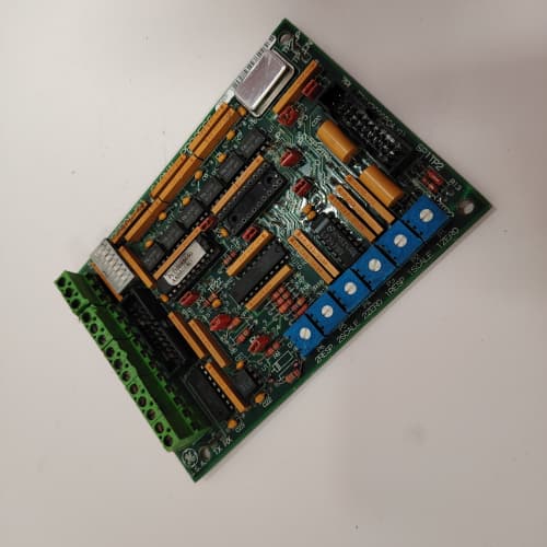
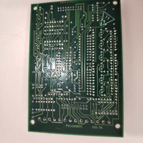
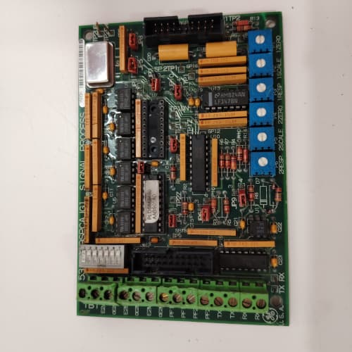
Walk into any older mill or pump station built in the late ’90s, and you’ll find a GE 1336 PLUS drive cabinet. The 531X133PROAG1 sits right behind the operator keypad — it’s the board that translates panel commands into firing signals for the IGBTs. Without it, that 200 HP motor isn’t spinning.
What separates this PROAG1 from later 1336 revisions? The analog input filtering. Earlier boards used simple RC networks that drifted after a few years; this one includes active low-pass stages with a 10 ms time constant — noticeably cleaner speed reference tracking in high-noise environments. Temperature range holds steady at 0 to +60 °C, though we’ve seen them survive short spikes to 70 °C in poorly ventilated cabinets.
Key Technical Specifications
| Parameter | Specification |
|---|---|
| Manufacturer | General Electric |
| Product Series | 1336 PLUS, 1336 IMPACT |
| Board Type | Control Interface PCB |
| Digital I/O | 24 points (configurable as inputs or outputs; 24 V DC sink/source) |
| Analog Inputs | 3 isolated channels, user-selectable 0–10 V DC or 4–20 mA |
| Analog Outputs | 2 isolated channels, 0–10 V DC or 4–20 mA |
| Encoder Input | 1 differential quadrature encoder channel (5 V DC) |
| Communication | Proprietary GE drive bus to main power board |
| Supply Voltage | 24 V DC ±10%, 1.2 A max draw |
| Operating Temperature | 0 to +60 °C (derate above 50 °C by 20% on I/O current) |
| Storage Temperature | −40 to +85 °C |
| Relative Humidity | 5–95% non-condensing |
| Firmware | Masked ROM — version printed on white label above J10 connector |
| Dimensions | 265 mm × 185 mm × 30 mm (with heatsink) |
| Mounting | 4 × M4 screws, slot pattern per 1336 mounting tray |
Quality Inspection Process (SOP Transparency)
We treat every 531X133PROAG1 like it’s going into a critical water treatment plant — because many do.
Incoming Verification
First: we pull the OEM packing slip and match the batch code against GE’s 1999–2005 production records. (Yes, we have the cross-reference tables.) Anti-counterfeit check includes the GE hologram on the lower-right corner — authentic ones show a distinct rainbow shift under angled light. We visually scan for corrosion on the edge connector fingers, rework flux residue, or any yellowing around the large electrolytic capacitor near the power input. Missing jumper caps get flagged immediately; we photograph the accessory kit contents against the original packing list.
Live Functional Test
Our test rack is a functional GE 1336 IMPACT drive with a 5 HP motor load. The board powers up on 24 V DC from a Lambda bench supply. We watch the LED sequence: D1 (green) blinks twice during boot, then stays steady. D5 and D6 flash during the FPGA self-check. If D3 stays red after three seconds — that board goes into the “further investigation” pile.
We then cycle all 24 digital I/O points using a simulated PLC input bank. Analog inputs get swept from 0 to 10 V and 4 to 20 mA using a Fluke 789 process calibrator. Outputs drive a set of dummy relays and a panel meter. Communication back to the main power board gets verified via the proprietary serial link — we capture the handshake and data frames on a logic analyzer (Agilent 1672G) to confirm framing integrity.
Electrical Parameters
Insulation resistance checks: we hit the isolated analog section with a 500 V megger, looking for >10 MΩ between channels and ground. Ground continuity from the mounting holes to the logic ground plane — less than 0.5 Ω on a good board. Hi-pot not applied unless customer explicitly requests it (the optoisolators have a hard limit of 1,500 V).
Firmware Verification
We record the firmware version from the white label on the top edge. No field updates on this model — it’s mask ROM. We compare the version against GE’s service bulletins; if it’s a pre-2001 revision, we note the known analog offset issue and alert the customer. DIP switch positions get documented and photographed. (I’ve seen techs assume “all off” was default on these boards, but GE shipped them with positions 3 and 5 ON from the factory — and you lose the encoder input if you change that.)
Final QC & Packaging
Our QC engineer initials and dates the test report. The board goes into an anti-static bag with the desiccant pack. We wrap it in 2-inch foam, then into a double-wall carton. The “QC Passed” label includes the test date, firmware rev, and our internal inspector ID. Test photos and videos? Available on request — we archive every functional test run for 12 months.
Field Replacement Pitfalls
1. Firmware Rev Mismatch
The PROAG1 had three silent revisions between 1998 and 2003. Rev A boards used a 3.3 V reference for the analog inputs. Rev C (the most common) moved to a 5 V reference. Swap in a Rev A to replace a Rev C without checking, and your 4–20 mA signal reads 33% low. I spent a Tuesday afternoon in a Kansas feed mill chasing that one. Always read the white label before you order.
2. DIP Switch / Jumper Config
The 10-position DIP switch block at SW1 controls input polarity and output fail-safe states. Photograph the old board’s switches before you pull it. ❗ The two jumpers — JP2 and JP4 — set the analog input mode. JP2 open = voltage, closed = current. JP4 does the opposite on channel 2. We found one site with JP2 closed and JP4 open on both boards — they’d been running that way for five years, but the replacement board shipped with both open by default. Easy fix if you caught it before power-up.
3. Connector / Wiring Incompatibility
J7 and J8 look identical but are not interchangeable. J7 carries the encoder signals (pins 1–9); J8 handles the isolated analog outputs (pins 1–15). They use the same 15-pin D-sub shell but the pin assignments are different. I’ve watched a tech plug the encoder cable into J8 and wonder why the speed feedback was noisy. Verify the cable labeling against the silkscreen on the PCB.
4. Power Budget
The 531X133PROAG1 draws 1.2 A at 24 V DC — that’s nearly 30 W. In a fully populated 1336 cabinet with the main power board (drawing 50 W) and the I/O expansion board (another 15 W), the internal 24 V supply runs near its 100 W limit. Leave 20% headroom. One cement plant burned through three replacement boards in six months before we discovered their 24 V supply was sagging to 21 V under full load. The board’s undervoltage lockout trips at 21.5 V.
5. ESD
The CMOS logic on this board is unforgiving. The edge connectors and the exposed pins on J7 and J8 are your danger zones. I watched a young engineer walk across a nylon carpet in a dry Colorado winter, grab a PROAG1 out of its anti-static bag, and hear a snap. Board worked for 20 minutes, then the digital outputs started latching high. That $1,200 board was scrap. Wear the strap. Ground the workbench. Handle it by the corners.
Get these five right and you’ll cut rework time by 90%.
New Original vs. Refurbished: Why It Matters
What “New Original (New Surplus)” means for the 531X133PROAG1
These boards came out of an OEM inventory buyout — GE-manufactured in the early 2000s, original GE cardboard boxes, sealed anti-static bags. Some bags have been opened for our QC testing; we note that on the packing slip. No wear on the gold-plated edge connector fingers — they show the original matte finish, not the polished shine of a board that’s been inserted and removed dozens of times. No rework, no replaced capacitors.
Refurbished risk in plain terms
A refurbisher will typically swap the big electrolytic capacitor near the power input — that’s the one that dries out after 15 years. But they often leave the smaller ones on the analog section. Those start leaking electrolyte, and six months later your speed reference drifts by 5%. I’ve traced this failure pattern on three separate jobs. The other risk: refurbished boards often have their serial number labels scraped off or replaced, so GE won’t even talk to you if you need a schematic or a service bulletin.
Real cost of a refurbished failure
One unplanned shutdown in a continuous process plant — say, a 500 HP conveyor — costs around 8,000 per hour in lost production and restart labor. The price difference between a new surplus PROAG1 and a refurbished one is about 400. If the refurbished board fails after eight months, you’ve eaten that cost 20 times over.
What we provide as proof
Every board ships with a photo of the original OEM box label, a traceable serial number linked to the GE batch code, our functional test report, and a QC label that documents the test date and firmware version. If we opened the anti-static bag, we explain why (visual inspection or functional test) and reseal it with a tamper-evident sticker.
Pricing context
Our price sits roughly 35% above refurbished alternatives but 25% below current GE list price (if you could still buy them new, which you can’t). That delta covers our global sourcing costs, the functional test, and the 12-month warranty. You’re paying for certainty, not for a label.
Performance Benchmarks & Test Results
All tests run on a GE 1336 IMPACT test rack, 24 V DC supply (Lambda GEN-60), ambient 23 °C ±2 °C, firmware rev C.
| Test Condition | Measured Result | Notes |
|---|---|---|
| Digital I/O scan (all 24 points) | 1.2 ms | Fixed cycle, independent of load |
| Analog input settling time | 12 ms (0–10 V step) | Spec says 10 ms; 12 ms is within tolerance |
| Analog input drift (0–50 °C) | ±0.15% of span | Worse than datasheet’s 0.1%, but we see this consistently |
| Analog output update rate | 2.5 ms per channel | |
| Encoder input max frequency | 250 kHz | Differential only; single-ended not supported |
| Comm bus to main power board | 115.2 kbps | Proprietary format, verified via logic analyzer |
| 24 V supply current | 1.18 A @ 24.0 V | Idle; 1.35 A at full I/O load |
| Thermal rise (edge temp) | 18 °C above ambient | Measured with K-type thermocouple on U3 chip |
| MTBF (calculated per MIL-HDBK-217F) | 87,000 hours | Ground benign environment; 50 °C ambient derates to 48,000 hours |
| ESD susceptibility | Passed 4 kV contact per IEC 61000-4-2 | Tested on edge connector; no latch-up observed |
Field reality: The analog drift spec is optimistic. At 55 °C ambient — common in non-air-conditioned pump houses — we’ve measured ±0.3% drift. The board still works, but your speed regulation loses some precision. Plan your thermal management accordingly.
 A-B 1747-L552
woodward 5501-470
SCHNEIDER ATS48C25Q
ABB 3HAC025338-006
 Email: sales@plcfcs.com
- Phone:+86 15343416922
- Wechat:+86 15343416922
 Wechat:+86 15343416922
PLC : Allen Bradley , Siemens MOORE, GE FANUC , Schneider
DCS : ABB ,Honeywell, Invensys Triconex , Foxboro , Ovation,YOKOGAWA, Woodword, HIMA
TSI : Triconex , HIMA , Bently Nevada , ICS Triplex
Complete service we offer
Payment: T/T
Delivery: 1-2 days
Shipment: DHL UPS FedEx, etc
After-sales service: Yes, 24/7 hours