 Email: jiedong@sxrszdh.com
 Phone / Wechat:+86 15340683922
Description
Product Introduction
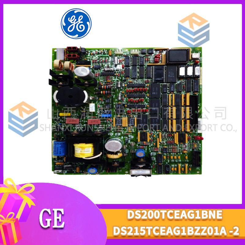
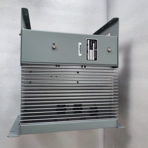
The DS4815DTDB is the digital workhorse of the Mark V system—32 channels of discrete I/O on a single board. It reads limit switches, pushbuttons, and proximity sensors, and drives status lights, small relays, and pilot solenoids. You’ll find these scattered across the I/O rack, handling everything from turbine lube oil pump status to burner management interlocks.
Compared to the DS4815DTD (non-B revision), the “B” adds a small but important hardware change: the output stage was redesigned with lower on-resistance MOSFETs (0.15Ω vs. 0.25Ω), which reduces heat generation by about 20% at full load. The input threshold was also tightened from 10V to 12V ON, improving noise immunity in high-EMI environments. The terminal assignment is identical—direct drop-in. No firmware changes required; the CPU sees the board as the same type.
Key Technical Specifications
| Parameter | Value / Range |
|---|---|
| Digital Inputs | 16, optically isolated, 24V DC (sourcing/sinking configurable) |
| Input Voltage Range | 18–32 VDC |
| Input Current (Typical) | 5 mA at 24V DC |
| Input ON Threshold | > 12V DC (improved from 10V) |
| Input OFF Threshold | < 6V DC |
| Input Delay (ON/OFF) | 5 ms (typical), configurable filter up to 50 ms |
| Digital Outputs | 16, high-side switching, 24V DC |
| Output Current (Continuous) | 0.75 A per channel |
| Output Current (Peak, 100ms) | 1.5 A per channel |
| On-State Resistance | < 0.15Ω (typical) |
| Output Protection | Short-circuit (foldback), overtemp (85°C), overvoltage (36V clamp) |
| Inductive Load Protection | Built-in flyback diode per output (1A rating) |
| Total Output Current (All Channels) | 8 A maximum (backplane-limited) |
| Isolation (Channel-to-GND) | 1500 VAC |
| Status Indicators | 32 LEDs (green for input, green/amber for output per channel) + Power (green), Fault (red) |
| Termination | 2 x 18-pin spring-clamp terminal blocks |
| Coating | Conformal-coated |
| Power Supply | 24 VDC from backplane (isolated) |
| Operating Temp | 0°C to +60°C |
| Dimensions (W x H x D) | 280 x 120 x 40 mm (11.0 x 4.7 x 1.6 in) |
Compatible Replacement Models
| Model | Classification | Notes & Labor Estimate |
|---|---|---|
| DS4815DTDB | ✅ Drop-in Replacement | Target model. Same form factor and terminal block. No changes. |
| DS4815DTD | ✅ Drop-in Replacement | Earlier revision—slightly higher on-resistance; lower noise immunity. Direct swap. |
| DS4815DTD-5 | ✅ Drop-in Replacement | Variant with 5VDC inputs for TTL-level sensors. Check voltage before installing—not compatible with 24V systems. |
| DS4815DTDC | ✅ Drop-in Replacement | Plant-reported variant with external surge suppression—functionally identical to B. |
| IS420UIOBH4A | ❌ Hardware Incompatible | Mark VIe universal I/O module—different architecture. Not compatible. |
Frequently Asked Questions (FAQ)
Q: What’s the difference between the DTDB and the DTD?
The “B” revision has lower on-resistance outputs (0.15Ω vs. 0.25Ω), which means less voltage drop and less heat at 0.75A. The input ON threshold was raised from 10V to 12V, making the board less susceptible to noise. In practical terms, if you’re running all 16 outputs at 0.75A, the DTD will generate about 3W of heat in the output drivers; the DTDB generates about 2.3W—a noticeable difference in a tight cabinet. We’ve seen DTD boards in 55°C ambient run at 75°C case temperature; the DTDB runs at 68°C.
Q: Can the digital inputs handle 48V DC?
No—the inputs are rated for 18-32V DC. Feeding 48V will damage the optocouplers. We’ve seen plants incorrectly wire 48V from an old PLC system and smoke three input channels. If your field devices are 48V, use an interposing relay with a 24V coil—let the relay convert the voltage.
Q: The output LED is green, but the load isn’t energized. What’s the first thing to check?
Measure the voltage at the load terminals. At 0.75A, the board’s on-resistance (0.15Ω) drops about 0.1V, but the bigger drop is in the wiring. If you’re using 18 AWG wire over 100 feet, the round-trip resistance is about 0.2Ω, dropping another 0.15V. Combined, you might see 23.75V at the load. If your load requires at least 22V (80% of 24V), that’s fine. If you’re reading 0V, check the external power supply—the DTDB’s outputs are switched 24V from the field supply, not from the backplane. If the field supply is off, the LEDs will still light (they indicate the switch state, not actual voltage).
Q: The input LED is on, but the CPU shows the signal as OFF. What’s the likely cause?
The CPU samples the inputs at the beginning of each scan cycle (typically 10-50 ms). The input has a 5ms delay. If the input signal is pulsing faster than the scan time, the CPU may miss it. This is common with proximity sensors on fast-moving machinery. Check the input delay setting—you can set it to 0ms (no filter) in the I/O map, but then you’ll be susceptible to noise. For high-speed applications, consider using a dedicated high-speed input module (e.g., DS4815HSCG).
Q: The fault LED is red on power-up. How do I troubleshoot?
Solid red usually indicates a short-circuit on one or more output channels. The board detects a short by measuring the output current (it’s above 2A for more than 100ms). The offending channel will have an amber LED. To clear the fault, remove the short, then cycle power to the board (pull and re-insert, or power-cycle the rack). If the fault persists without any field wiring connected, the board’s internal output driver may have failed—usually due to a transient voltage spike. Contact us for repair or replacement.
Q: Can I mix input and output wiring on the same terminal block?
Yes—the terminal blocks are physically adjacent. GE’s terminal assignment is: inputs 1-16 on terminals 1-32 (two terminals per channel: + and -), outputs 1-16 on terminals 33-64. It’s common to have input wiring right next to output wiring. Just be careful with routing—output wires carrying 0.75A can induce noise into input wiring if they’re bundled together for long runs. We recommend a 2-inch separation in the cabinet and using shielded cable for inputs if they’re in the same conduit.
Q: What’s the total current limit for all 16 outputs?
8A total across all outputs. That’s limited by the board’s PCB traces and the backplane’s 24V power distribution. The backplane can supply 30A total, so the DTDB is well within that. If you need more than 8A total, you’ll need to split the load across two boards. For example, 10 channels at 0.75A = 7.5A—still within limit. 12 channels at 0.75A = 9A—that would exceed the board’s rating. GE recommends a maximum of 10 channels at full load to keep the traces below 70°C.
Q: Can I use the DTDB for 120V AC loads?
No—the outputs are 24V DC only. Switching AC loads with a DC output will cause arcing and destroy the MOSFETs. If you need to control 120V AC loads, use an external relay (24V DC coil) and drive the relay with the DTDB’s output. The relay contacts handle the AC current. We’ve seen plants try to drive small AC fans directly—the fans lasted about a week before the MOSFETs shorted.
Q: Does the DTDB support output read-back?
No—the board doesn’t have current sensing. The LED indicates the commanded state, not the actual state. If the output is shorted, the LED will still show green, but the CPU won’t know there’s a fault (except through the red Fault LED). For applications where you need load diagnostics, use a higher-end output module like the DS4815CHGA (which has current sensing).
Q: What’s the input impedance and how does it affect the loop?
The input impedance is about 4.8kΩ (24V / 5mA). That’s standard for most PLC inputs. If you’re using a 2-wire proximity sensor, the leakage current of the sensor must be less than the input OFF threshold. Most sensors have leakage below 1mA, so you’re fine. If the sensor has high leakage (some older inductive sensors), it might keep the input ON even when it should be OFF. You can add a 2.2kΩ resistor in parallel with the input to reduce the effective impedance and pull the voltage down.
Q: What’s the lead time for a surplus DTDB?
We keep 5-8 units in stock—this is one of the most common Mark V boards. Domestic: 2-3 business days ground, overnight if ordered by 2 PM EST. International: 5-7 days via DHL, with customs potentially adding 1-3 days. This board is not ITAR-controlled, so we can ship to most countries without an export license. We include a GE certificate of origin and commercial invoice with every shipment. If you need the board urgently for a critical outage, we can arrange expedited shipping—contact us for options.
A-B 2711P-B10C4D8
ABB SNAT604IFS 61029052
FANUC A06B-0293-B010
A-B 1771-ACNR15
 Email: sales@plcfcs.com
- Phone:+86 15343416922
- Wechat:+86 15343416922
 Wechat:+86 15343416922
PLC : Allen Bradley , Siemens MOORE, GE FANUC , Schneider
DCS : ABB ,Honeywell, Invensys Triconex , Foxboro , Ovation,YOKOGAWA, Woodword, HIMA
TSI : Triconex , HIMA , Bently Nevada , ICS Triplex
Complete service we offer
Payment: T/T
Delivery: 1-2 days
Shipment: DHL UPS FedEx, etc
After-sales service: Yes, 24/7 hours