 Email: jiedong@sxrszdh.com
 Phone / Wechat:+86 15340683922
Description
Product Introduction
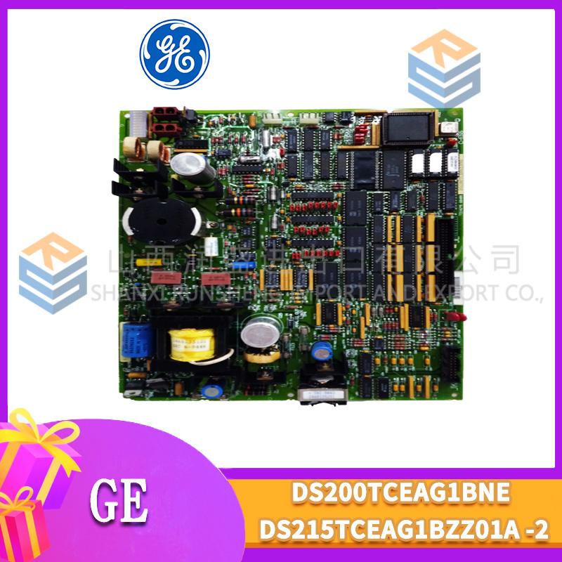
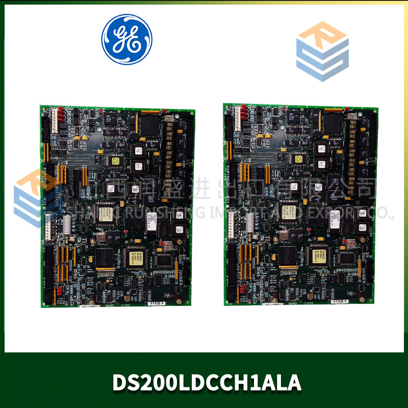
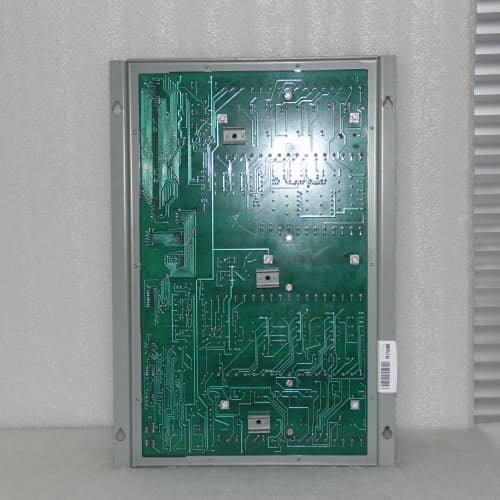
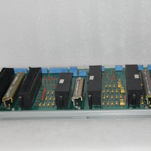
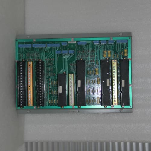
The DS3880TIMC is the workhorse that connects the Mark VI CPU to the actual turbine hardware. Think of it as the bridge between the control logic and the fuel valves, inlet guide vanes, and speed sensors. It’s a hybrid module—part I/O, part signal conditioner, part actuator driver—that consolidates functions that would otherwise require multiple separate boards. You’ll typically find it in the Mark VI rack, usually in slot 1 or 2, directly adjacent to the CPU.
Compared to the DS3880TIM (non-C revision), the “C” brings several significant hardware and firmware upgrades: the actuator drive channels now support both 4-20mA and ±10V output (the older unit was 4-20mA only). The speed detection front-end was completely redesigned with a faster comparator and adjustable threshold (down to 100mV), improving low-speed reliability. The onboard memory doubled from 2MB to 4MB to support more complex actuator control algorithms. The terminal block assignment changed slightly—the actuator output terminals are now labeled differently, but the pin functions are largely the same. Re-wiring is not required for most installations, but verify the new labeling if you’re upgrading. The firmware interface is compatible with CPU v7.0 and higher.
Key Technical Specifications
| Parameter | Value / Range |
|---|---|
| Speed Inputs | 2 x magnetic pickup/encoder channels, independently isolated |
| Speed Frequency Range | 0.5 Hz to 10 kHz |
| Speed Threshold (Adjustable) | 100mV to 25V (software-selectable) |
| Analog Outputs | 8 channels, 4-20mA or ±10V (software-selectable per channel) |
| Analog Output Resolution | 14-bit (0.006% of range) |
| Analog Output Accuracy | ±0.1% of full scale at 25°C |
| Digital Inputs | 8, optically isolated, 24V DC (sinking/sourcing) |
| Digital Outputs | 8, high-side switching, 24V DC @ 0.5A |
| Actuator Drive Channels | 2 x redundant, 4-20mA or ±10V (software-selectable) |
| Actuator Drive Current | Up to 20mA (loop-powered), or ±10V (high impedance) |
| Backplane Interface | VME-style 128-pin connector |
| Diagnostics | Speed sensor fault detection, actuator output read-back, digital I/O status |
| Status LEDs | Power (green), Fault (red), Speed 1/2 (green flashing), Actuator 1/2 (amber), Comms (flashing green) |
| Termination | 2 x 18-pin spring-clamp terminal blocks |
| Coating | Conformal-coated |
| Power Supply | 24 VDC from backplane (isolated) |
| Operating Temp | 0°C to +60°C |
| Dimensions (W x H x D) | 280 x 120 x 40 mm (11.0 x 4.7 x 1.6 in) |
Compatible Replacement Models
| Model | Classification | Notes & Labor Estimate |
|---|---|---|
| DS3880TIMC | ✅ Drop-in Replacement | Target model. Verify firmware compatibility (v7.0 or higher). |
| DS3880TIM | ⚠️ Software Compatible | Earlier revision. 4-20mA outputs only, 2MB memory, fixed speed threshold. Hardware fits, but you may need to re-flash firmware and adjust actuator loop tuning. Budget 2-4 hours for re-tuning and verification. |
| DS3880TIMA | ⚠️ Software Compatible | A field-identified intermediate revision. Likely shares the C’s terminal assignment but lacks the high-output drive capability. Verify with GE. |
| DS3880TIO | ❌ Hardware Incompatible | A different TIM variant with fixed I/O configuration—not a replacement. |
| IS420UCSBH4A | ❌ Hardware Incompatible | Mark VIe universal controller—different architecture. Not compatible. |
Frequently Asked Questions (FAQ)
Q: What’s the primary function of the TIMC compared to other I/O boards?
The TIMC is the “front door” to the turbine. Unlike standard I/O boards that just handle analog or digital signals, the TIMC is specifically designed for turbine-specific functions: speed sensing (with conditioner), actuator control (with output drive and position feedback), and turbine protection I/O. It’s the board that actually closes the loop on fuel control—the CPU calculates the fuel demand, and the TIMC translates that into a 4-20mA signal to the fuel valve actuator, then reads back the valve position. That combination makes it essential.
Q: Can I use the TIMC for steam turbine applications?
Yes, but with a few considerations. The TIMC is primarily designed for gas turbines, but it works equally well for steam turbines—you’ll use the speed inputs for shaft speed, the analog outputs for governor valve control, and the digital I/O for trip relays and status signals. However, steam turbines typically use different actuator characteristics (slower response, larger strokes) and may require different PID tuning. The TIMC’s firmware supports both; you just need to configure the actuator type in the software.
Q: The speed input is showing intermittent signal dropout at low speed. What’s the likely cause?
The TIMC’s speed threshold is software-adjustable from 100mV to 25V. If your magnetic pickup outputs 200mV at low speed but the threshold is set to 500mV, you’ll miss pulses. Measure the pickup’s output with an oscilloscope at the minimum operating speed (e.g., turning gear speed). Set the threshold to 50% of that value, with hysteresis at 25% of the threshold. The C revision’s improved comparator handles this better than the older TIM—but if your sensor output is still too low, consider a high-output pickup or a preamplifier.
Q: The actuator output reads 4mA when it should be 12mA. What’s causing this?
Check the actuator’s power supply. The TIMC’s analog outputs are not loop-powered—they require an external 24V supply for 4-20mA loops. If the actuator isn’t getting power, the output will read 0mA (or near 4mA due to leakage). Also, check the output configuration: the TIMC can be set to 4-20mA or ±10V per channel. If it’s set to ±10V but you’re measuring current, you’ll get no reading. Use the Toolbox to verify the output mode.
Q: What’s the difference between the analog outputs and the actuator drive channels?
The analog outputs (8 channels) are general-purpose—they can be used for any 4-20mA or ±10V signal (e.g., control loops, positioners, or retransmission). The actuator drive channels (2 channels) are specialized: they include additional diagnostic feedback (actuator current and voltage read-back) and are designed for higher accuracy and faster response (the actuator channels have a 20µs update rate vs. 100µs for the general-purpose outputs). The actuator drive channels are typically used for the primary fuel and inlet guide vane actuators, while the general-purpose outputs are used for auxiliary controls.
Q: Can I use the TIMC’s digital outputs to directly drive solenoids?
Yes—but be mindful of the 0.5A current limit. If your solenoid draws more than 0.5A continuous, use an interposing relay. The TIMC’s digital outputs are high-side switching with built-in flyback diodes, so they handle inductive loads up to 0.5A without external protection. For larger solenoids (e.g., fuel trip solenoids that draw 1-2A), use an external relay and let the relay contacts handle the current. We’ve seen plants try to drive 1A solenoids directly and burn out the output driver.
Q: The Fault LED is red, and the actuator channel is not working. How do I diagnose this?
The red Fault LED could indicate (1) an overcurrent on the actuator output, (2) an open loop (broken wire), or (3) an internal overtemperature. First, disconnect the actuator wiring and set the output to 12mA. If the Fault LED clears, the actuator is shorted or has a low impedance. If the fault persists, check the internal temperature using the Toolbox—the TIMC has an onboard sensor. If it’s above 80°C, the board may be overheating—check airflow and ambient temperature. If none of these, the output driver IC may have failed.
Q: Does the TIMC require calibration?
Yes—specifically the analog outputs and the speed threshold. GE recommends a 2-year calibration cycle for the analog outputs (verify 4mA and 20mA points). The speed threshold is set in software and doesn’t drift, but the sensor’s output amplitude varies with gap and temperature. For best reliability, check the speed signal at low speed annually using an oscilloscope and adjust the threshold accordingly. If the TIMC is used in a safety-critical application (fuel control), we recommend annual calibration—it’s a 30-minute procedure using GE’s Toolbox and a precision current source/voltmeter.
Q: Can the TIMC be used in a hot-standby redundant configuration?
Yes, the TIMC supports dual-redundant operation. In a 2-out-of-2 voting scheme, you’d have two TIMC boards in the rack, each receiving the same sensor signals and driving the same actuators through OR-ing diodes. The CPU selects the primary based on the status (heartbeat). If one TIMC fails, the other takes over—switchover is typically <100ms. However, this requires a specific rack configuration—check GE’s manual GEK-108565 for wiring details. Not all plants use redundant TIMCs; it’s typically found in critical applications (e.g., nuclear or high-value turbines).
Q: I’m upgrading from a TIM to a TIMC. Do I need to update the application logic?
Not necessarily—the TIMC is backward-compatible with the TIM’s I/O map. The additional features (e.g., ±10V output) are optional and won’t affect your existing logic if you don’t use them. However, if you’re using the actuator drive channels, you may need to re-tune the PID gains because the TIMC’s output drivers have a slightly faster response time (20µs vs. 50µs). We’ve seen plants that needed to adjust the derivative term by 10-15% after the upgrade. Test the new setup on a simulator before going live.
Q: What’s the lead time for a surplus TIMC?
We keep 3-5 units in stock. Domestic: 2-3 business days ground, overnight if ordered by 2 PM EST. International: 5-7 days via DHL. This board is subject to ITAR regulations—we’ll need an end-user certificate for international shipments. For domestic orders, no license is required. We include a GE certificate of origin and a commercial invoice with each shipment. If you need the board urgently, we can arrange expedited shipping—contact us directly for options.
 Email: sales@plcfcs.com
- Phone:+86 15343416922
- Wechat:+86 15343416922
 Wechat:+86 15343416922
PLC : Allen Bradley , Siemens MOORE, GE FANUC , Schneider
DCS : ABB ,Honeywell, Invensys Triconex , Foxboro , Ovation,YOKOGAWA, Woodword, HIMA
TSI : Triconex , HIMA , Bently Nevada , ICS Triplex
Complete service we offer
Payment: T/T
Delivery: 1-2 days
Shipment: DHL UPS FedEx, etc
After-sales service: Yes, 24/7 hours