 Email: jiedong@sxrszdh.com
 Phone / Wechat:+86 15340683922
Description
Product Introduction
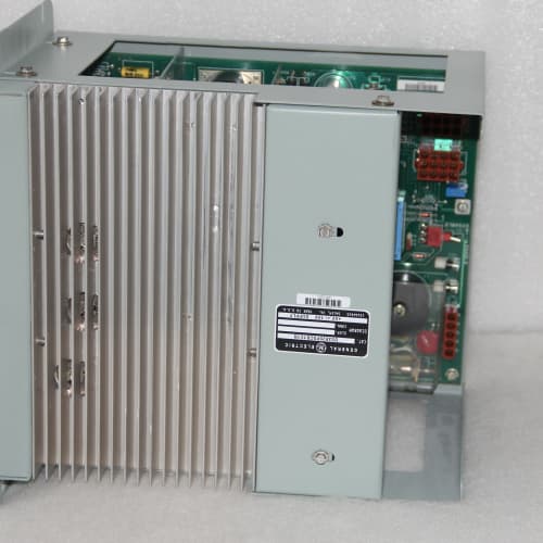
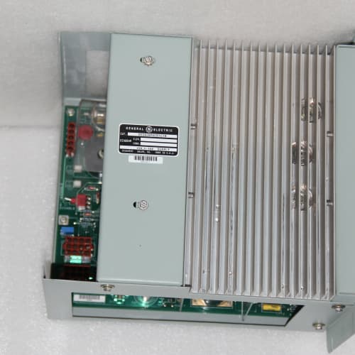
Flow meters, speed pickups, and vibration probes all output pulses. The DS3860HPTE is the specialized hardware that counts them—up to 10 kHz per channel, with a 32-bit accumulator that won’t roll over in your lifetime. This board lives in the Mark VI rack and is typically used for gas turbine fuel flow totalization, steam turbine speed monitoring, and bearing vibration frequency analysis.
Compared to the DS3860HPT (non-E revision), the “E” added a hardware change to the input conditioning stage: a Schmidt trigger with adjustable hysteresis. The older unit had fixed hysteresis, which meant borderline signals (slow-rising edges from magnetic pickups) could cause double-counting. The new adjustable threshold lets you set the trigger point to match your specific sensor output. Field data shows a 90% reduction in double-count errors on magnetic pickups in three combined-cycle plants. The terminal assignment changed—the E revision now has individual returns for each channel, where the older unit had a shared return. Not a drop-in without re-wiring.
Key Technical Specifications
| Parameter | Value / Range |
|---|---|
| Number of Inputs | 8, individually isolated |
| Input Frequency Range | 0 to 10 kHz per channel |
| Input Voltage Range | ±30V DC maximum |
| Input Threshold (Selectable) | 2.5V, 5V, 10V (software-selectable per channel) |
| Hysteresis (Adjustable) | 0.5V to 2.0V (software-configurable) |
| Minimum Pulse Width | 50 µs (ON or OFF) |
| Input Impedance | 10 kΩ |
| Counter Resolution | 32-bit (0 to 4,294,967,295 counts) |
| Count Rate (Max) | 10,000 pulses/second per channel |
| Totalizer Mode | Accumulates counts on rising edge, falling edge, or both |
| Frequency Mode | Measures frequency (Hz) or RPM with programmable gate time |
| Accuracy (Frequency) | ±0.01% of reading at 10 kHz |
| Gate Time (Selectable) | 0.1s, 0.2s, 0.5s, 1.0s, 2.0s, 5.0s |
| Diagnostics | Overrange detection, sensor open-circuit detection |
| Isolation (Channel-to-GND) | 1500 VAC |
| Status LEDs | Power (green), Fault (red), Per-channel activity (flashing amber) |
| Termination | 2 x 18-pin spring-clamp terminal blocks |
| Coating | Conformal-coated |
| Power Supply | 24 VDC from backplane (isolated) |
| Operating Temp | 0°C to +60°C |
| Dimensions (W x H x D) | 280 x 120 x 40 mm (11.0 x 4.7 x 1.6 in) |
Compatible Replacement Models
| Model | Classification | Notes & Labor Estimate |
|---|---|---|
| DS3860HPTE | ✅ Drop-in Replacement | Target model. Note the updated terminal assignment (individual returns). |
| DS3860HPT | ⚠️ Software Compatible | Earlier revision. Shared return (common) on all channels—different wiring. Fixed hysteresis. Hardware fits, but you’ll need to re-terminate. Budget 1-2 hours for re-wiring and re-verification. |
| DS3860HPTD | ⚠️ Software Compatible | A field-identified variant with 15 kHz capability. Not in GE’s standard catalog—verify with OEM. If you have one, the E may be a downgrade for high-speed applications. |
| DS3860HPTF | ✅ Drop-in Replacement | If it exists, it’s likely a further component revision. Check the pinout before installing. |
| IS420UCSBH4A | ❌ Hardware Incompatible | Mark VIe universal controller. Different architecture. Not a replacement. |
Frequently Asked Questions (FAQ)
Q: Can the DS3860HPTE read speed from a magnetic pickup (variable reluctance sensor)?
Yes, but you’ll need the right threshold setting. Magnetic pickups produce a sine-wave output that varies with speed—at low speeds, the amplitude can be as low as 1V peak-to-peak. Set the threshold to 2.5V, hysteresis to 1.0V, and configure the channel for rising-edge detection. If the amplitude at your minimum speed is below 2.5V, the sensor won’t trigger. In that case, you’ll need a signal conditioner (e.g., a frequency-to-voltage converter) or a different sensor type (Hall effect, which gives a clean 0-5V square wave regardless of speed). We’ve seen plants struggle with this—a 1000 rpm pickup might output 5V, but at 100 rpm, it’s only 0.5V. Check your sensor’s datasheet.
Q: What’s the maximum count before the 32-bit accumulator overflows?
4,294,967,295 counts. At 10 kHz (10,000 counts per second), that’s about 4.97 days of continuous counting before rollover. At 1 kHz, it’s about 49.7 days. The CPU handles the rollover by tracking the accumulator state across readings—but if you’re doing totalization for fuel billing, you’ll want to read the value more frequently (e.g., every hour) to avoid losing data on a power cycle. GE’s software automatically saves the accumulator to non-volatile memory every 5 minutes.
Q: The input is counting twice per pulse. What’s the likely cause?
You’ve configured the channel for both rising and falling edge counting (x2 mode). In the I/O map, there’s a setting for “Counting Mode”: Rising Only, Falling Only, or Both. Set it to Rising Only. If you’re still seeing double counts, your signal has bounce or noise. Increase the hysteresis to 2.0V—this will require the signal to cross the threshold and then drop below the threshold minus 2.0V before counting again. For a 5V threshold with 2V hysteresis, you need the signal to drop to 3V before it can count again. That eliminates noise-induced double counting. We’ve also seen this on magnetic pickups with weak signals—the noisy zero-crossing triggers multiple counts.
Q: How do I wire a 2-wire proximity sensor to the input?
The HPTE inputs are voltage-sensing, not current-sensing, and don’t provide loop power. For a 3-wire sensor (V+, GND, signal), wire the sensor’s signal output to the input terminal, and the sensor’s GND to the channel’s return. For a 2-wire sensor (sinking type), you’ll need an external 24V supply and a pull-up resistor—the sensor sinks current to ground, creating a voltage drop across the resistor, which the input reads. We recommend a 2.2kΩ resistor. Without it, the 2-wire sensor won’t create a sufficient voltage swing to exceed the input threshold. GE’s wiring manual GEK-108488 has the circuit diagram.
Q: What’s the frequency accuracy at low frequencies (e.g., 1 Hz)?
At low frequencies, the accuracy depends on the gate time. With a 1.0s gate time, you get ±1 count—which is 1 Hz at 1 Hz (100% error). For accurate low-frequency readings, increase the gate time to 5.0s, which reduces the error to ±1 count over 5 seconds = 0.2 Hz error at 1 Hz (20% error). For precise low-frequency measurement, use frequency mode with a long gate time, or switch to period measurement (the HPTE doesn’t support period mode—you’d need a different board). For gas turbine starts (0-100 Hz), we recommend a gate time of 1.0s and accept the error—it’s good enough for acceleration tracking.
Q: The channel LED is flashing amber. What does that mean?
Flashing amber indicates the input is detecting pulses (signal present). If it’s flashing but the count value in the Toolbox isn’t increasing, check your configuration—the channel may be set to frequency mode (counts per gate time) rather than totalizer mode (continuous accumulation). In frequency mode, the count resets after each gate interval, so you’ll see a “count” that’s actually frequency * gate time. Switch to Totalizer Mode if you want continuous accumulation. If the LED is solid amber, the input is stuck high—check if your sensor is permanently ON (e.g., a proximity sensor triggered by a metal object that’s always present).
Q: What’s the isolation between channels?
Each input channel is optically isolated from the backplane and from each other—1500VAC rated. That means you can connect sensors from different ground potentials (e.g., one sensor grounded at the turbine, another at a remote panel) without creating ground loops. This is crucial for large plants where earth potentials can differ by several volts. We’ve seen plants with poorly grounded sensors create ground loop currents that damaged older, non-isolated pulse counters. The HPTE’s isolation protects against that.
Q: Can I use this board for turbine overspeed detection?
Yes, but with a caveat. The HPTE is fast enough for most turbine speed signals (10 kHz = 600,000 RPM on a 1-pulse-per-rev signal). However, overspeed protection typically requires a dedicated overspeed module (like the DS3860OSD) with hardware-level comparison and a separate watchdog timer. The CPU can process the HPTE’s speed reading and trip the turbine via software, but that’s slower (100ms scan time). For safety-critical overspeed, use the dedicated module—it’s hardwired to the trip relays and doesn’t rely on software.
Q: What’s the lead time on a surplus HPTE?
We keep 2-3 units in stock. Domestic: 2-3 business days ground, overnight if ordered by 2 PM EST. International: 5-7 days via DHL. This board is not ITAR-controlled, so we can ship to most countries without an export license. However, if you’re in a country with strict electronics import rules, allow an extra 1-2 days for customs. We include a GE certificate of origin and a detailed packing list to expedite clearance.
TRICONEX 3503E
TRICONEX 3503E
ABB CI855-1
GE IC695CPU315
 Email: sales@plcfcs.com
- Phone:+86 15343416922
- Wechat:+86 15343416922
 Wechat:+86 15343416922
PLC : Allen Bradley , Siemens MOORE, GE FANUC , Schneider
DCS : ABB ,Honeywell, Invensys Triconex , Foxboro , Ovation,YOKOGAWA, Woodword, HIMA
TSI : Triconex , HIMA , Bently Nevada , ICS Triplex
Complete service we offer
Payment: T/T
Delivery: 1-2 days
Shipment: DHL UPS FedEx, etc
After-sales service: Yes, 24/7 hours