 Email: jiedong@sxrszdh.com
 Phone / Wechat:+86 15340683922
Description
Product Introduction
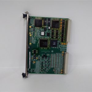
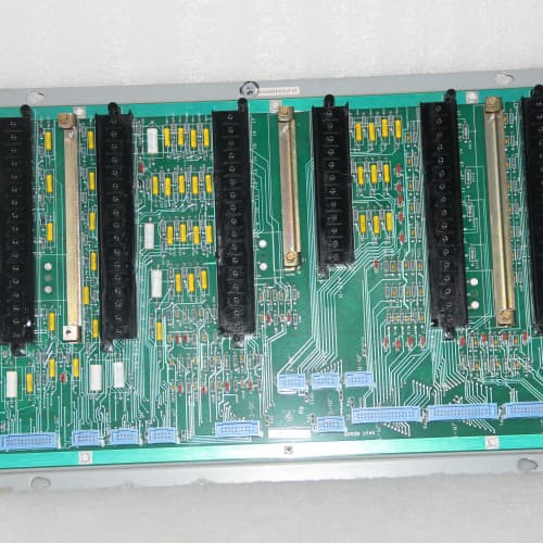
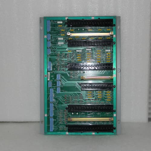
The GE DS3820RDMA is a relay output module for the Speedtronic Mark V turbine control system, providing 16 independent, isolated dry-contact outputs for driving external field devices. This board mounts directly into the Mark V rack and interfaces with the backplane, receiving logic-level commands from the CPU or communication processor and converting them to isolated relay closures suitable for solenoids, contactors, alarm annunciators, and actuator pilot circuits.
The RDMA uses Form A (SPST-NO) electromechanical relays with 2A contact rating, individually opto-isolated from the backplane logic to prevent electrical noise or faults in the field wiring from affecting the control processor. Each output channel includes a status LED that indicates when the relay coil is energized, and an external power input terminal block allows each group of eight channels to use separate field supply voltages. This module is widely used in Mark V systems for trip and permissive logic, valve positioning commands, and discrete alarms. We stock the RDMA because it remains one of the most frequently replaced Mark V output cards—relay contacts wear out, but board-level electronics rarely fail.
Key Technical Specifications
| Parameter | Value |
|---|---|
| Manufacturer | GE (General Electric) |
| Model Number | DS3820RDMA |
| Series | Speedtronic Mark V |
| Number of Channels | 16 (organized as two banks of 8) |
| Output Type | Form A (SPST-NO) electromechanical relays |
| Contact Rating | 2A at 250 VAC / 30 VDC (resistive load) |
| Contact Material | Silver alloy with gold flash (low-level switching compatible) |
| Minimum Load | 10 mA at 5 VDC (for oxide-fracture performance) |
| Coil Voltage | 24 VDC (derived from field supply input) |
| Field Supply Inputs | Two independent terminals (one per bank of 8 channels) |
| Field Supply Range | 18-32 VDC |
| Coil Current per Relay | 15 mA typical (240 mA per bank when all 8 energized) |
| Isolation Voltage | 2500 VDC (field-to-backplane) |
| Response Time | 10 ms typical (energize), 5 ms typical (de-energize) |
| Mechanical Life | 10 million operations (unloaded) |
| Electrical Life | 100,000 operations at rated 2A load |
| Status Indicators | 16 green LEDs (one per channel, coil-energized indication) |
| Operating Temperature | 0 to +60°C (ambient, forced air required) |
| Storage Temperature | -40 to +85°C |
| Dimensions | 8.5″ x 4.2″ x 1.5″ (standard Mark V 1-slot width) |
| Connector | 96-pin DIN 41612 (Type C, male) + external terminal block for field wiring |
Key Selling Points & Differentiators
- 16 isolated outputs in a single slot. Banks of 8 channels with separate field supply inputs allow mixing 24V and 48V DC loads in the same module. Most competitive systems require multiple cards to get this channel density.
- Individual channel status LEDs. Each relay has a dedicated green LED that illuminates when the coil is energized. This is critical for field troubleshooting—you can verify command presence at the module before checking field wiring, halving diagnostic time during outages.
- Gold-flash contacts for low-level switching. Standard industrial relays with pure silver contacts can fail to conduct at low voltages (<5V) due to oxide buildup. The RDMA’s gold-flash contacts are specifically designed for dry-circuit switching and low-energy signals—a common failure point we see in third-party replacements.
- External field supply input allows mixed voltages. You can feed 24 VDC to bank 1 and 48 VDC to bank 2 in the same module. This accommodates mixed legacy and modern field devices without requiring separate modules or external interposing relays.
- 48-hour burn-in with full channel cycling. Every unit runs through a complete functional test: all 16 channels cycled 1,000 times at rated load (2A, 24V DC resistive), with contact resistance measured at 100-cycle intervals. We reject any relay showing contact resistance above 100mΩ or bounce exceeding 2ms.
- 18-month warranty covering relay contact integrity and coil operation. We warranty the module against welded contacts, open coils, and output failures. If a relay fails under specified conditions, we cross-ship a replacement. Note that contact wear due to excessive inductive loads or incorrect field supply voltage is not covered—we help you size the load correctly to avoid that.
Frequently Asked Questions (FAQ)
Q: This RDMA is a relay output module. Can I use it for high-current loads like motor contactors or solenoid valves?
A: Yes, but with careful attention to contact rating and inductive load protection. The relays are rated at 2A at 250 VAC or 30 VDC resistive. For inductive loads (solenoids, contactor coils, motor starters), derate to 1A to account for inrush and back-EMF. You must install a suppression diode (DC loads) or snubber (AC loads) across each load—otherwise, inductive kickback can arc across the relay contacts, causing pitting and premature failure. We’ve seen plants burn out RDMA contacts in six months because they skipped the diodes. We include a suppression diode selection guide with every board.
Q: I have a DS3820RDMB in my rack. Is the RDMA a direct replacement?
A: Yes—the RDMA and RDMB are functionally identical and mechanically interchangeable. The “A” and “B” are revision codes that indicate minor component sourcing changes. The B revision used a different relay manufacturer (Omron instead of Fujitsu) but the specs, pinout, and terminal block connections are identical. You can mix A and B revisions in the same Mark V chassis without any issues. The only difference is the date code on the relays. If you’re replacing a failed RDMB with this RDMA, it’s a direct drop-in—no firmware, configuration, or wiring changes.
Q: How do I connect external power to the RDMA? I see two field supply terminals but no details.
A: The RDMA has a dedicated field wiring terminal block on the top edge of the board. You’ll see two terminal pairs labeled “FIELD SUPPLY BANK 1” (pins A1-A2) and “FIELD SUPPLY BANK 2” (pins B1-B2). Provide 18-32 VDC at each bank—the same voltage you intend to switch on the relay outputs. The coil for each relay runs on this field supply; the contact common terminal is internal. You cannot mix AC and DC across banks—both banks must be DC, but they can be different DC voltages (e.g., bank 1 at 24V, bank 2 at 48V). The field supply is isolated from the backplane, so you can float it or ground it per your site’s practice. Do not exceed 32V or you will overdrive the relay coils.
Q: What happens when the relay contacts weld shut? Can I manually reset or unstick them?
A: To be frank—no. Once a relay contact welds, the relay is mechanically damaged and must be replaced. This is one of the most common failure modes on RDMA boards, almost always caused by switching inductive loads without proper suppression. The relay contacts physically melt and fuse together from the arc energy. There is no reset button or software override. If you suspect a welded contact, power down the cabinet, remove the board, and check continuity across the normally-open contacts with the coil de-energized. If you have continuity (near zero ohms), the relay is welded. We recommend replacing the entire board and installing proper suppression on the faulty load. We offer a refurbishment service where we replace individual relays, but it’s usually faster to swap in a tested spare board.
Q: Can I use a solid-state relay equivalent instead of this electromechanical RDMA?
A: There is no GE solid-state equivalent for the RDMA in the Mark V family. If you want solid-state outputs, you’d need to switch to a different module family (like the Mark VI series) or install external solid-state relays between the RDMA and your loads. The RDMA is electromechanical by design because GE intended it for applications requiring galvanic isolation and low contact resistance—solid-state outputs have leakage current and on-resistance that can interfere with some legacy field devices. That said, if you’re driving purely DC loads at low current (<0.5A), you could replace the RDMA with a third-party solid-state relay module and rewire the backplane, but that’s a custom modification—not something we support or recommend.
Q: How many contact operations can I expect from this board before relays fail?
A: The mechanical life is rated at 10 million cycles (unloaded), but electrical life at rated 2A load is 100,000 cycles. In real-world Mark V applications, most RDMA boards last 5-8 years before they reach 100,000 operations, depending on how often the outputs cycle. Trip and interlock outputs typically cycle rarely (a few times per week), so they last nearly indefinitely—we’ve seen original RDMA boards from 1995 still in service. But outputs used for valve modulation or burner management that cycle every minute can hit 100,000 operations in under 3 months. For high-frequency applications, we recommend external interposing relays between the RDMA and the load—the RDMA drives the interposing relay (low current), and the interposing relay handles the high-cycle load. We have a white paper on this topic we can send you.
Q: Does this board require any configuration or setpoint adjustments before installation?
A: No—the RDMA is a purely digital output module. It has no dip switches, jumpers, or potentiometers. The Mark V CPU writes a logic 1 to a specific memory address, the backplane sends a 24V signal to the corresponding relay coil, and the contact closes. There are no configurable parameters. However, the Mark V configuration file must be set to recognize the RDMA’s backplane slot address and mapping. If you’re replacing an existing board in the same slot, no changes are needed. If you’re adding it to a new slot, you’ll need to update the Mark V software configuration to map the outputs. We can provide the backplane addressing table for the RDMA—contact support with your system’s serial number.
Q: I need to switch 120 VAC loads. Can the RDMA handle AC loads?
A: Yes—the RDMA contacts are rated for 2A at 250 VAC resistive. For AC inductive loads (motors, transformers), derate to 1A and install an RC snubber (typically 100Ω and 0.1µF in series) across the contacts. The relay contact material (silver alloy with gold flash) is suitable for AC applications without special treatment. However, note that the field supply inputs are DC only (18-32 VDC). The relay coils are DC. The contacts themselves can switch AC or DC independent of the coil supply. The external field power you bring in to drive the coils is DC; the load side can be AC. Just don’t use the field supply terminals for AC—that will damage the coil drive circuit.
Q: Do you test every relay on the RDMA boards you sell?
A: Yes—absolutely. Our standard test procedure for the RDMA involves cycling all 16 relays 1,000 times at 2A/24VDC resistive load, monitoring contact resistance and bounce at 100-cycle intervals. We also test the external field supply inputs with both 24V and 32V to ensure the coil drive circuit regulates correctly. We check each status LED for brightness and correct energization timing. Our QC report includes a contact resistance matrix (all 16 channels measured before and after cycling) and a functional test pass/fail summary. We reject boards where any relay shows contact resistance above 100mΩ or bounce above 2ms. All our units ship with this QC report, which your QA department can file for traceability.
A-B MPL-B580F-MJ72AA
WESTINGHOUSE 5X00300G02
ABB AI625
Woodward 5501-470
 Email: sales@plcfcs.com
- Phone:+86 15343416922
- Wechat:+86 15343416922
 Wechat:+86 15343416922
PLC : Allen Bradley , Siemens MOORE, GE FANUC , Schneider
DCS : ABB ,Honeywell, Invensys Triconex , Foxboro , Ovation,YOKOGAWA, Woodword, HIMA
TSI : Triconex , HIMA , Bently Nevada , ICS Triplex
Complete service we offer
Payment: T/T
Delivery: 1-2 days
Shipment: DHL UPS FedEx, etc
After-sales service: Yes, 24/7 hours