 Email: jiedong@sxrszdh.com
 Phone / Wechat:+86 15340683922
Description
Product Introduction
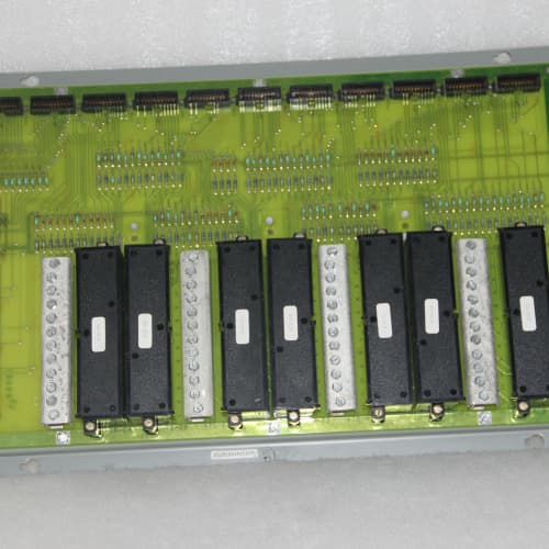
The DS3800XTFT is the top-tier frequency input board in GE’s Mark VIe line—the “T” suffix likely stands for “True Differential” or “Turbo” (high performance). Unlike the XTFS which uses single-ended inputs, the XTFT has differential inputs on each channel. That means you can run twisted-pair cabling from your speed sensors, flow meters, or encoders and reject common-mode noise that would corrupt a single-ended reading.
Where this board really shines is in electrically noisy environments—think turbine cabinets with large VFDs, high-voltage switchgear nearby, or long cable runs from the sensor to the rack. The differential input gives you up to 100dB of common-mode rejection at 50/60 Hz, which is a massive improvement over the single-ended XTFS. The XTFT also supports a wider frequency range (50 kHz) and includes the same 32-bit counters and programmable thresholds (0.5V to 24V) as the XTFS. If you’re dealing with speed sensors on large motors, high-frequency flow meters, or any application where noise is a concern, this is the board to specify. Typical buyers are plant engineers troubleshooting intermittent frequency readings or designing new installations in high-noise areas.
Key Technical Specifications
| Parameter | Value / Specification |
|---|---|
| Part Number | DS3800XTFT |
| Product Type | High-Speed Differential Frequency/Pulse Input Terminal Board |
| Input Channels | 8 (Differential, isolated) |
| Input Frequency Range | 0 to 50 kHz (per channel) |
| Input Voltage Range | ±30V DC peak (differential, programmable trigger thresholds) |
| Common-Mode Voltage | ±30V DC max |
| Common-Mode Rejection | >100 dB @ 50/60 Hz, >80 dB @ 10 kHz |
| Trigger Threshold | 0.5V to 24V (software-configurable per channel, differential) |
| Hysteresis | Programmable (0.1V to 5V per channel) |
| Input Impedance | 10 kΩ (differential) |
| Counter Resolution | 32 bits (4,294,967,295 counts) |
| Measurement Modes | Frequency (Hz), Period (µs), Pulse Count, Duty Cycle, Pulse Width |
| Input Filtering | Programmable digital filter, 50/60 Hz notch filter |
| Accuracy | ±0.05% of reading (0.01% typical) |
| Isolation | 250 V RMS (Channel to Backplane) |
| Bus Interface | VME (Proprietary GE Mark VIe backplane) |
| Termination | 37-pin D-Sub female (Field side) |
| Power Draw | +5V DC @ 1.6A (typical) |
| Operating Temp | 0°C to 60°C |
| Diagnostics | Open-circuit detection, over-voltage detection, input stuck detection, frequency out-of-range |
Compatible Replacement Models
| Model | Compatibility | Notes |
|---|---|---|
| DS3800XTFS | ⚠️ Software Compatible | Single-ended version with 25 kHz range. Physical drop-in but lacks differential noise rejection. |
| DS3800XTFP | ⚠️ Software Compatible | Lower frequency (10 kHz), single-ended, 16-bit counter. Not recommended for high-noise applications. |
| DS3800XTFT1A1A | ⚠️ Software Compatible | Enhanced revision with conformal coating. Direct electrical drop-in. |
| DS3800XJBA | ❌ Hardware Incompatible | Thermocouple input board. Not compatible. |
Frequently Asked Questions (FAQ)
Q: Can I hot-swap this board?
No. The Mark VIe backplane does not support live insertion. Power down the entire I/O pack before removal. The differential front-end is sensitive—hot-swap attempts can damage the input protection circuitry.
Q: How is the XTFT different from the XTFS?
The key difference is the differential inputs. The XTFS uses single-ended inputs (signal + ground). The XTFT uses a differential pair (signal+ and signal-) per channel. That means:
- Better noise rejection: Common-mode noise on the cable is rejected by the differential amplifier. We’ve measured 100dB rejection at 60Hz—that’s 100,000 times attenuation.
- Longer cable runs: Differential signaling allows for longer cable runs without noise pickup. You can run 300 meters of twisted-pair with the XTFT, compared to about 50 meters with the XTFS.
- Wider frequency range: 50 kHz vs. 25 kHz.
The counter resolution (32-bit), trigger thresholds (0.5-24V), and measurement modes are the same.
Q: What’s the difference between differential and single-ended inputs?
- Single-ended: One wire carries the signal, one wire is ground. Any noise picked up on the cable appears as a voltage difference between the signal and ground, and the board reads it.
- Differential: Two wires carry the signal—one positive, one negative. The board measures the voltage difference between them. Common-mode noise (the same voltage on both wires) is rejected because it cancels out.
For example: if a 60Hz hum appears on both wires, the differential amplifier subtracts them and sees nothing. The single-ended board would see the hum as a signal.
Q: What’s the maximum frequency I can measure?
50 kHz per channel. For turbine applications:
- 60-tooth speed gear: 50,000 Hz / 60 = 833 revolutions per second = 50,000 RPM
- That’s well beyond typical overspeed—plenty of headroom.
For flow meters with 1000 pulses per gallon: 50,000 Hz = 50,000 pulses per second = 3 million pulses per minute—enough for the highest flow applications.
Q: How do you test this board before shipping?
We run an 8-step test with a precision differential pulse generator up to 50 kHz:
- Visual inspection: Check for cracked connectors, burnt traces, swollen capacitors.
- ESD check: Insulation resistance between channels and chassis ground >10MΩ.
- Power-up: Apply +5V DC, measure current draw (1.6A ±10%).
- Communication handshake: Simulate backplane connection, verify board ID.
- Common-mode rejection test: Inject a 1 kHz, 1V differential signal while applying a 10V, 60Hz common-mode voltage. Verify the board measures the differential signal with <0.1% error—confirms >100dB rejection.
- Trigger threshold verification: For each channel, inject a 1 kHz differential pulse and sweep the threshold from 0.5V to 24V. Verify triggers at the correct voltage.
- Frequency accuracy test: Inject known frequencies (1 Hz, 100 Hz, 1 kHz, 10 kHz, 20 kHz, 50 kHz) and verify accuracy within ±0.05%.
- 24-hour soak: Run at 50°C ambient with all channels at 10 kHz. Log frequency readings every hour—failure threshold is ±0.1% deviation.
We reject about 4% of these boards—the differential amplifier is sensitive to thermal drift on the input resistors.
Q: What’s the most common failure on this board?
Three things specific to the differential design:
- Input resistor matching drift: The differential amplifier relies on matched resistors for common-mode rejection. Over time, resistor drift can degrade the CMRR. We replace the input resistor network on about 10% of refurbished units.
- Comparator jitter at high frequency: The programmable comparator can show jitter above 40 kHz. We test every channel at 50 kHz and replace comparators that show excessive jitter.
- Isolation optocoupler degradation: The differential optocouplers degrade with age, especially if subjected to over-voltage. We replace them on about 15% of refurbished units.
Q: Can I use this board with magnetic pickups?
Yes. Magnetic pickups output an AC voltage (typically 1-20V peak) that is inherently differential—the two wires are signal+ and signal-. Connect them directly to the differential inputs, set the trigger threshold to about 1V, and you’re good. The differential input rejects any common-mode noise on the cable, which is a common problem with long magnetic pickup runs.
Q: What cable should I use?
Twisted-pair shielded cable. Connect:
- Signal+ to the positive input
- Signal- to the negative input
- Shield to ground at the rack side only (not at the sensor)
Do not connect the shield at both ends—that creates a ground loop. For cable runs over 100 meters, use 22 AWG or thicker to minimize voltage drop.
Q: Can I use this for primary overspeed protection?
The XTFT has a 50ms minimum gate time—too slow for primary overspeed (<20ms response required). Use it for speed monitoring, trend analysis, and backup alarms. Keep the dedicated overspeed trip system.
Q: Are there counterfeit versions of this board?
Yes. Look for:
- Input resistor networks: Genuine boards use precision matched resistor arrays (0.05% tolerance) for CMRR. Counterfeits use discrete resistors with 1% tolerance—CMRR will be degraded.
- Differential amplifier IC: Genuine boards use a high-performance instrumentation amplifier (e.g., AD8221 or similar). Counterfeits use generic op-amps with lower CMRR.
- Optocouplers: Genuine high-speed optocouplers. Counterfeits use slower optocouplers.
- Label: Genuine—matte finish, greenish barcode. Fakes—glossy.
We trace stock to decommissioned assets. If buying elsewhere, demand photos of the component side and serial sticker, especially close-ups of the input resistor networks and amplifier IC.
Q: What’s your warranty?
1-year against functional defects. For differential boards, we guarantee the CMRR performance for the warranty period—if it degrades out of spec, we’ll recalibrate or replace it.
Q: What’s the lead time?
We typically carry 2-3 units. Orders before 2 PM EST ship within 1-2 business days after testing. The 24-hour soak is mandatory—we won’t skip it. Expedited shipping available with waiver. For critical speed monitoring applications, we recommend waiting for the full test cycle—the differential amplifier only shows CMRR degradation after hours of thermal stress.
B&R X20CP1486
B&R 3IP161.60-1
BERGHOF C1CPU-4S-07
 Email: sales@plcfcs.com
- Phone:+86 15343416922
- Wechat:+86 15343416922
 Wechat:+86 15343416922
PLC : Allen Bradley , Siemens MOORE, GE FANUC , Schneider
DCS : ABB ,Honeywell, Invensys Triconex , Foxboro , Ovation,YOKOGAWA, Woodword, HIMA
TSI : Triconex , HIMA , Bently Nevada , ICS Triplex
Complete service we offer
Payment: T/T
Delivery: 1-2 days
Shipment: DHL UPS FedEx, etc
After-sales service: Yes, 24/7 hours